Designing a Printed Circuit Board (PCB) for Radio Frequency (RF) applications is vastly different from designing a board for typical digital logic applications. Even small changes in layout geometry or component selection can make the difference between a board that achieves the desired performance vs one that underperforms or is prone to instability or oscillations.
Especially in the crowded and noisy RF spectrum of modern times, achieving the maximum link budget for sensitivity and range, signal integrity, EMI/EMC compliance, and minimizing signal losses are critical RF PCB design goals.
Managing parameters like transmission line properties and impedance matching accurately across the RF signal chain on a PCB impacts overall system performance. The following are twenty key factors RF circuit board designers need to evaluate and control throughout the design phase:
1. Operating Frequency
The RF PCB layout approach varies tremendously across the frequency spectrum. For lower HF or VHF bands surface traces still suffice, while UHF+ frequencies need microstrips or striplines in dielectric substrates. The higher the frequency, the smaller structures and tighter design tolerances become.
| Band | Frequency Range |
|---|---|
| HF | 3 MHz – 30 MHz |
| VHF | 30 MHz – 300 MHz |
| UHF | 300 MHz – 1000 MHz |
| Microwave | > 1 GHz |
2. Wavelength vs Dimensions
The wavelength of the RF signal must be considered relative to the physical PCB dimensions. If board size exceeds roughly λ/10 then radiative effects will occur without special layout provisions. The frequency impacts all spacing and geometry.
3. Dielectric Constant (Dk)
The dielectric layer material heavily influences the impedance and velocity of RF traces. Materials with stable Dk allow controlled impedance traces to be created. Common substrates for RF use are FR4 (Dk4.5), Rogers (Dk3), and ceramic filled PTFE composites.
4. Loss Tangent

Dielectric materials have inherent losses indicated by the loss tangent (Df). Choosing a material with a low Df minimizes insertion losses in transmission lines. Glass microfiber substrates offer exceptional loss properties well suited for exacting wireless apps.
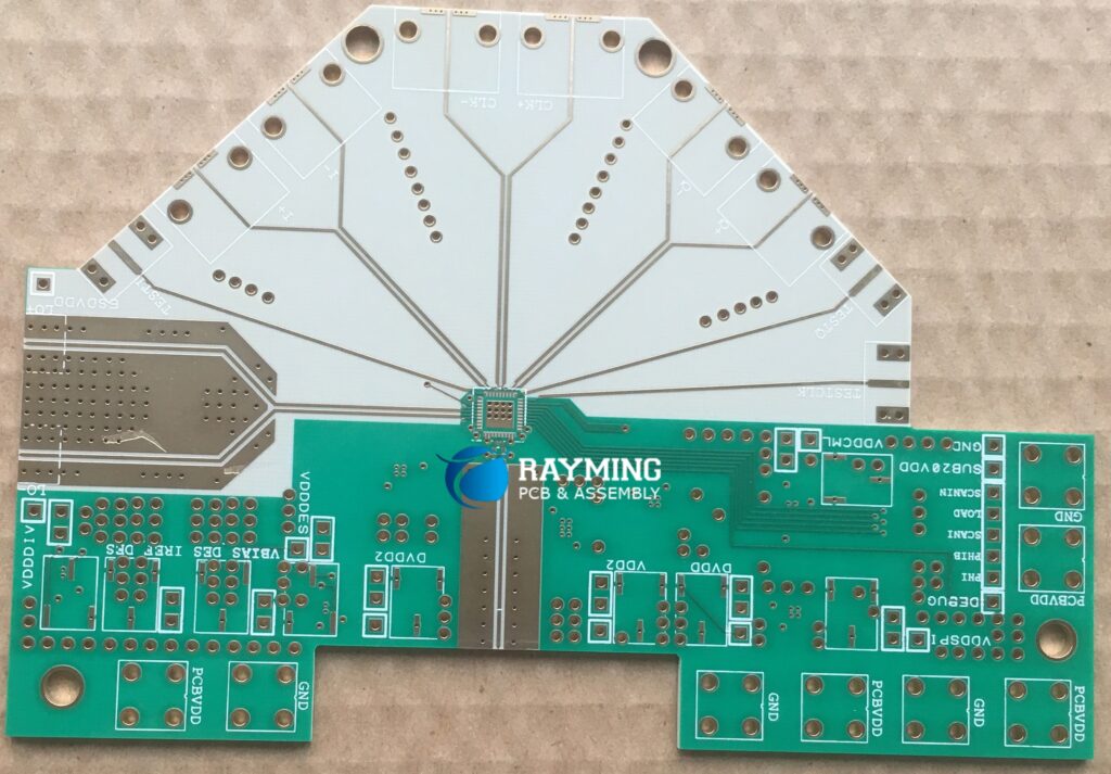
5. Stack-up and Layer Count
A well designed layer stack is vital for RF performance. Key considerations are –
- Signal layers use tightly controlled dielectrics
- Ground plane layers provide shielding and heat sinking
- Power integrity ensured through supply filter traces
- 6 to 12 layers needed for high frequency RF
6. Transmission Line Properties
Maintaining the desired characteristic impedance (Zo) and ensuring matched propagation velocities for different RF paths is mandatory. This requires accurately modeling transmission line parameters like strip width, gap width, conductor thickness, and anti-pad sizes.
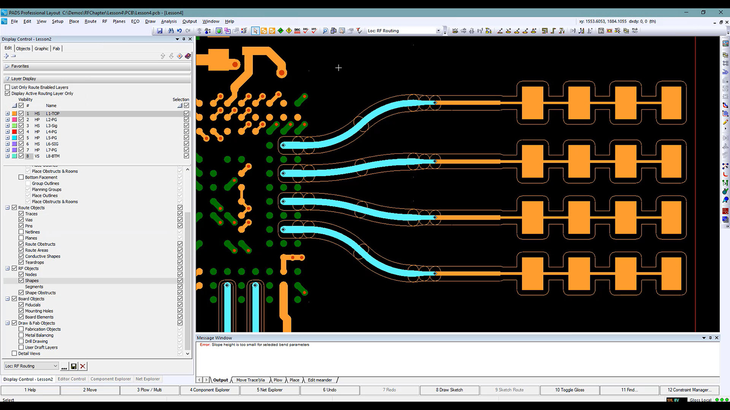
7. RF Trace Routing
Routing RF traces require special attention to distance between the lines. Keeping high frequency traces at λ/20 spacing up to λ/10 wavelength interval avoids coupling between traces. Shorter connections minimize insertion loss.
8. Controlled Impedance Lines
Nearly all RF signals need controlled impedance lines to minimize reflections back into the source. This necessitates precise modeling and adherence to dielectric thickness, copper weight, and trace dimensions chosen during layout.
9. Minimizing Bends and Vias
Whenever possible RF traces should use 45°/90° bends instead of arcs. Vias should also be avoided mid-trace unless fully RF modeled. Steps help minimize disruption of the transmission line properties.
10. Reference Planes
Including solid, continuous copper reference planes (GND) on adjacent layers shields the RF signal layers from noise coupling and radiative losses. Minimal reference plane gaps are essential.
11. Shielding & Isolation
Enclosing RF sections in grounded copper walls or cans provides isolation from nearby digital or analog circuits, preventing electromagnetic interference.
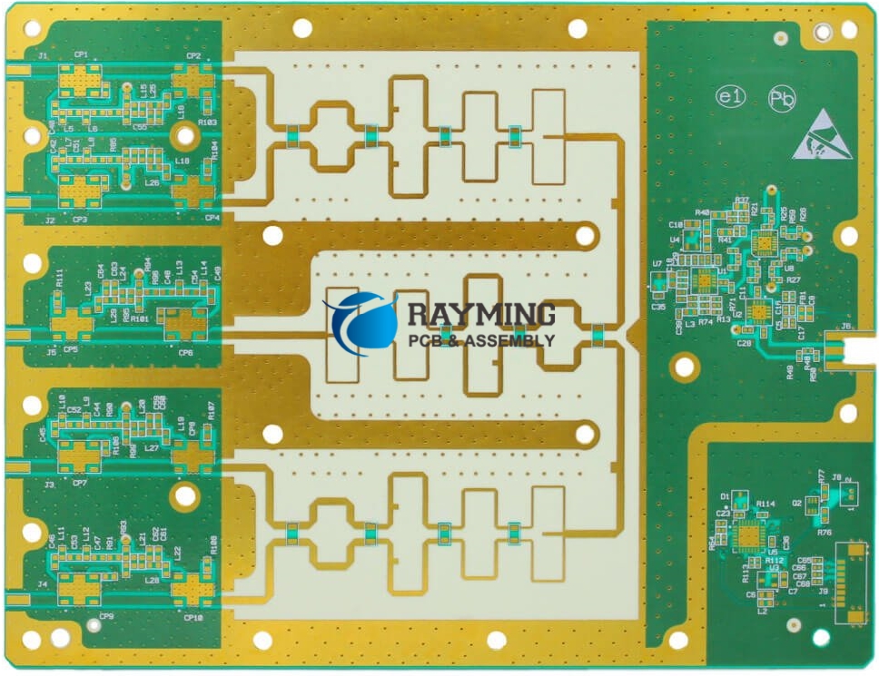
12. RF Filters
Low pass, bandpass, high pass, and directional filters implemented through the PCB layout keeps harmonic frequencies and band noise from impacting RF performance. This purification of frequency response is vital in radios.
13. Impedance Matching
As RF signals encounter discontinuities from traces to pads, vias, and components, abrupt impedance mismatch causes problematic signal reflections. Careful component footprint design and geometries that provide tapered impedance matching alleviates this issue.
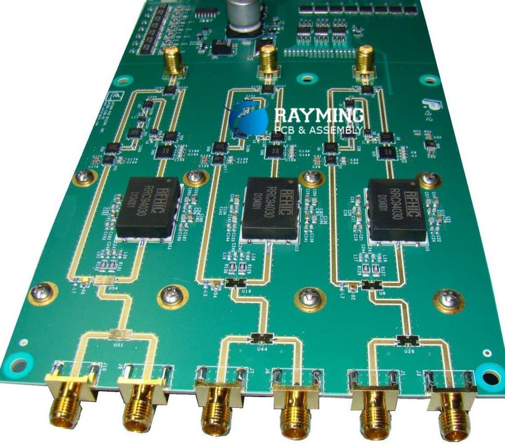
14. Thermal Management
Since RF semiconductors run relatively hot compared to digital ICs, having sufficient thermal pads, thermal vias, and uninterrupted ground planes to conduct heat away from dies is necessary. Thermal analysis should drive placement and layout decisions.
15. EMI Mitigation
EMI filtering components like chip inductors/capacitors and ferrite beads mounted strategically on the PCB combat electromagnetic interference emanating from or injecting into sensitive RF circuitry.
16. Signal Integrity
Applying sound high speed layout practices for termination resistors, timing alignment, ground planes, and tightly coupled signal return paths maintains signal integrity across RF traces, critical for error-free wireless transmission.
17. Component Selection
The operating frequency range determines ideal component selection. Whether ceramic SMT capacitors, chip inductors, semiconductor transistors, or electromechanical switches, parameters like Q factor, tolerance, and ESR must align with the RF design.
18. Manufacturing Process Control
Consistent dielectric thickness, reliable lamination, coplanarity, and mitigating PCB fabrication factors like undercut or skew are essential for repeatable RF performance. Tighter tolerances used here.
19. DFM Practices
Applying design for manufacturing guidelines tailored for RF applications minimizes production issues. Example – allowing adequate thermal relief gaps on large copper pours connected by thin traces or slots.
20. Testability Provisions
Incorporating test points, sockets, and other debug/validation provisions assist RF prototype tuning or diagnosing field issues. Accessible nodes in the RF signal chain prove invaluable for rapid iterations.
While this may seem an extensive list at first, with RF-centric design experience they become second nature. Let’s explore some examples of how these considerations manifest for different applications.
Bluetooth and Wi-Fi Application Example
For a 2.4GHz Bluetooth or Wi-Fi application transmitting up to 50m distance, the following RF design decisions may apply:
- Operating Frequency – 2.4 to 2.5GHz ISM Band
- Dielectric constant – FR4 material offers acceptable losses up to a few GHz
- Controlled impedance – Striplines with 50 ohms lines ($\pm$10%)
- 4 layer construction – Signal, GND, PWR, GND stackup
- Match line widths to achieve Zo target
- Reference planes on inner layers
- Bandpass filter to reject noise and harmonics
- Shielding on board extremities
- Impedance matching – e.g. tapered CPWG lines
- Via stitching connects top and bottom GND planes
Here the parameters enumerated before appear clearly influencing layout and component outcomes necessary to achieve the wireless range and reliability targets.
Next let’s examine a microwave radio link board where additional nuances emerge at 10+ GHz frequencies.
Microwave Radio Transceiver Example
For a 10GHz microwave radio with 1 to 5 km operating distance, the following considerations apply:
- Dielectric selection – Low loss substrate like Rogers RO4003C with stable Dk
- Very tight impedance control – 50Ω lines within ±5%
- Stripline transmission lines
- Extremely compact dimensions – components spaced at sub 1mm distances
- Minimize all trace lengths
- Shield partitions between transmitter and receiver sections
- Rigorous SI simulations performed – eye diagrams, S-parameters
- Thermal vias under RFICs
- EMI filters plus metal shield enclosure
- Micro-vias, stacked and blind vias used throughout
- Fine line PCB technology – traces/spaces ≤ 3/3 mils
- DFM analysis and review of panel utilization
Here the increased sophistication of modeling, material selection, fab process capability, and qualification testing required is self-evident compared to lower frequency boards.
In summary, by understanding and accounting for these twenty RF focused design criteria early in the PCB development process, RF performance goals can be met confidently. Pick the right PCB partner equipped with RF-centric design expertise, and your next wireless product’s success is virtually assured.
Frequently Asked Questions
Q1. What are some quick tips for catching common RF design issues before board fabrication?
Some quick best practices to catch RF issues early include – review dimensions relative to wavelength, check trace impedance variations stay <10%, look for adequate ground plane coverage (>60%) including via Stitching, use intentional periodic voids in copper rather than thermal spokes, and confirm reference planes do not shift between signal layers leading to cross-talk.
Q2. What could cause shift or loss of resonance frequency for an RF filter implemented through microstrip lines?
If the fabricated PCB RF filter resonant frequency shifts significantly (e.g. +- 5%), common causes could include tighter than modeled trace width and gaps leading to higher capacitance per inch than planned, dielectric thickness variation causing a velocity change, or material Dk being different than expected. Loss of filter rejection effectiveness outside the passband can similarly stem from impedance mismatches causing unexpected reflections and poor return loss.
Q3. When should you use blind and buried vias in RF designs?
For moderate RF frequencies under 6GHz, only if routing density demands it, as a thru-via is lower inductance. However for mmWave designs >20GHz, a thru-via’s inductance becomes disruptive necessitating buried/blind vias between layers with the barrels exposed on just top and bottom for component pads. Their shortened path offset inductance rise from the smaller micro-via hole size needed.
Q4. Why are 90 degree bends preferred over 45 degree bends for changing RF transmission line direction?
A 45 degree bend maintains the same characteristic impedance but does introduce noticeable phase delay, while a 90 degree bend has little delay. So when feasible right angle bends are preferred to avoid unintended phase shifts between RF paths that could impact modulation or resonance across a PCB sub-system.
Q5. When should you use an RF multilayer board vs a metal RF box enclosure?
If isolation from nearby digital components is required or radiative losses & EMI must be contained, then a shielded RF metal box enclosure with gaskets is necessary. But if adequate distance separation per wavelength can be maintained on a multilayer board, then inter-layer shielding traces or partitioning walls can suffice vs an external enclosure – minimizing size and cost.


