Introduction
Printed circuit boards (PCBs) are ubiquitous in all electronic devices and equipment. The base insulating material on which the copper traces are fabricated plays a crucial role in determining the performance and reliability of the PCB. The two most common materials used for fabricating PCB substrates are:
- FR4 – Flame retardant woven fiberglass reinforced epoxy resin
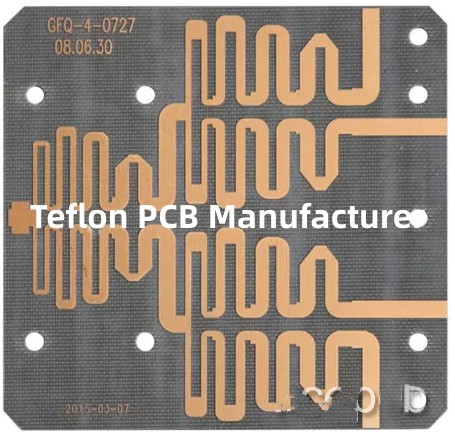
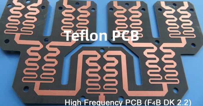
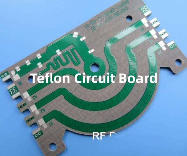
- PTFE – Polytetrafluoroethylene (Teflon)
Both offer distinct advantages and limitations when used as PCB substrates. This article provides a comparative analysis between PTFE and FR4 materials for PCB manufacturing.
Dielectric Properties
The dielectric constant and loss tangent are two key parameters that characterize the electrical insulation properties of the PCB substrate material.
Dielectric Constant
Dielectric constant indicates how easily the material can transmit an electric field. Lower dielectric constant allows faster signal propagation in PCB traces.
PTFE: Has a dielectric constant of 2.1, which is one of the lowest among plastics. This enables excellent high frequency performance.
FR4: Typical dielectric constant range is 4.2 – 4.8, nearly twice that of PTFE. Signal transmission is comparative slower.
Loss Tangent
Loss tangent quantifies the inherent signal loss in the dielectric when an AC signal passes through it. Lower loss tangent gives better signal integrity.
PTFE: Extremely low loss tangent of 0.0002 to 0.0005. Allows minimal signal loss even at high frequencies.
FR4: Has a loss tangent in the range of 0.01 to 0.025, much higher than PTFE. Causes higher signal loss and attenuation, especially at high frequencies.
Electrical Strength
This refers to the dielectric breakdown voltage that the PCB material can withstand before conduction occurs. Higher number indicates better insulation capability.
PTFE: Dielectric strength of 1000 V/mil. Can tolerate very high potential differences.
FR4: Typical dielectric strength values range from 300 – 500 V/mil. Has moderate voltage handling capacity.
Thermal Properties
Temperature tolerance and heat dissipation characteristics matter for PCB substrates.
Thermal Endurance
Determines the max temperature that can be continuously withstood without structural or electrical deterioration.
PTFE: Does not melt or deform until 327°C. Can survive very high temperatures.
FR4: Has a glass transition temperature of only 130°C to 170°C. Begins softening and deteriorating above this.
Thermal Conductivity
A measure of how well heat propagates through the material. Higher values mean better heat dissipation.
PTFE: Thermal conductivity around 0.25 W/m-K. Heat dissipation is moderate.
FR4: Slightly better thermal conductivity of 0.29 W/m-K. Allows somewhat superior heat dissipation.
Mechanical Properties
Mechanical rigidity, dimensional stability and flex resistance are also important PCB substrate attributes.
Flexural Strength
Indicates the bending force that can be sustained before permanent damage. Higher is better.
PTFE: Has a flexural strength of 55 MPa. Quite flexible but prolonged bending can cause issues.
FR4: Excellent flexural strength exceeding 125 MPa. Can withstand high degree of repeated bending.
Coefficient of Thermal Expansion (CTE)
Measure of dimensional change per degree temperature change. Should match copper traces to avoid structural stress.
PTFE: Low CTE of 17 ppm/°C. Very close match with copper CTE.
FR4: Typical values of 14-20 ppm/°C. Moderate CTE mismatch with copper.
Environmental Resistance
Ability to withstand humidity, chemicals, radiation etc. determines application range.
PTFE: Extremely hydrophobic and chemically inert. Unaffected by nearly all chemicals and environments.
FR4: Absorbs moisture and prone to degradation in humid or corrosive environments.
Radiation Tolerance
PTFE: Highly radiation resistant. Does not degrade easily under gamma, X-ray or other ionizing radiation.
FR4: Susceptible to damage and breakdown when exposed to high radiation doses.
Fabrication Factors
Manufacturability, solderability and cost differ between the two materials.
Drilling and Machining
PTFE: Difficult to drill and machine compared to FR4 due to its lower thermal conductivity. Requires diamond-tipped tools.
FR4: Easy to drill and machine using standard tools. Much lower wear on cutting tools.
Soldermask Adhesion
PTFE: Poor adhesion of soldermask to PTFE surface. Requires special adhesion promoters.
FR4: Soldermask adheres very well to the epoxy resin surface. No special treatment needed.
Solderability
PTFE: Non-wetting surface causes soldering issues. Surface etching or laser activation required to improve solderability.
FR4: Readily solderable without any surface treatment due to natural affinity of solder to the resin surface.
Cost
PTFE: More than 5 times costlier than FR4. Mainly used only when FR4 cannot meet technical requirements.
FR4: Very cost effective and widely used. Ideal choice for cost-driven commercial applications.
Typical Applications
PTFE PCBs are used when electrical performance, temperature tolerance or chemical resistance are critical factors:
- Aerospace and aviation electronics
- Automotive engine control units
- Down-hole oil well logging tools
- Medical implants and diagnostics devices
- Missile guidance systems
- Spacecraft avionics
FR4 PCBs are suitable for most common commercial applications:
- Computer motherboards and add-on cards
- Consumer electronics
- Industrial control systems
- Instrumentation and test equipment
- Internet-of-Things products
- Mobile devices
- Communication infrastructure
PTFE vs FR4 – Comparative Parameters
| Parameter | PTFE | FR4 |
|---|---|---|
| Dielectric Constant | 2.1 | 4.2 – 4.8 |
| Loss Tangent | 0.0002-0.0005 | 0.01 – 0.025 |
| Dielectric Strength (V/mil) | 1000 | 300-500 |
| Thermal Endurance (°C) | 327 | 130-170 |
| Thermal Conductivity (W/m-K) | 0.25 | 0.29 |
| Flexural Strength (MPa) | 55 | >125 |
| CTE (ppm/°C) | 17 | 14-20 |
| Moisture Absorption | Negligible | 0.2% |
| Chemical Resistance | Excellent | Moderate |
| Radiation Tolerance | High | Low |
| Drillability | Difficult | Easy |
| Soldermask Adhesion | Needs Promoter | Very Good |
| Cost | Very High | Low |
FAQs
What are some key benefits of PTFE PCBs over FR4?
PTFE offers superior electrical performance, temperature tolerance, chemical resistance, and radiation hardness compared to standard FR4 material. PTFE is the material of choice for extreme environment and mission-critical applications.
What are some downsides of using PTFE instead of FR4?
PTFE is very expensive, difficult to fabricate, and has lower flexural strength than FR4. PTFE also has poorer soldermask adhesion and solderability that require additional processing steps to overcome.
Why is PTFE PCB fabrication costlier than FR4?
PTFE is inherently costlier as a base material. Also, the specialized drilling, metallization, layer bonding, and surface treatments needed make its processing more complex and low yielding compared to FR4.
What are some key design considerations for PTFE PCBs?
Minimize small holes, closely spaced vias, and thin traces to limit drill wear out. Account for CTE mismatch with copper to avoid reliability risks. Use filled vias and thermal planes to aid heat dissipation.
What are some examples of harsh environments where PTFE PCBs are used?
Aerospace systems, oil well logging tools, automobile engine control units, medical implants, and defense electronics use PTFE PCBs because of their ability to survive extreme temperatures, vibration, chemicals and radiation.


