Microstrips and striplines represent common transmission line structures used in PCBs for routing high speed signals. Despite some superficial similarities, these two approaches have important distinctions in terms of construction, characteristics, modeling complexity and usage.
We will contrast these transmission line varieties across key factors:
- Construction
- Crosstalk
- Losses
- Modeling
- Signal integrity
- Routing considerations
- Applications
Analyzing pros and cons provides essential insight on selecting the optimal technique for a given PCB constraint budget based on lane quantity, data rates, acceptable loss performance, board construction cost and other critical design tradeoffs.
Construction

The distinguishing attributes of microstrips vs striplines lies in their physical structure:
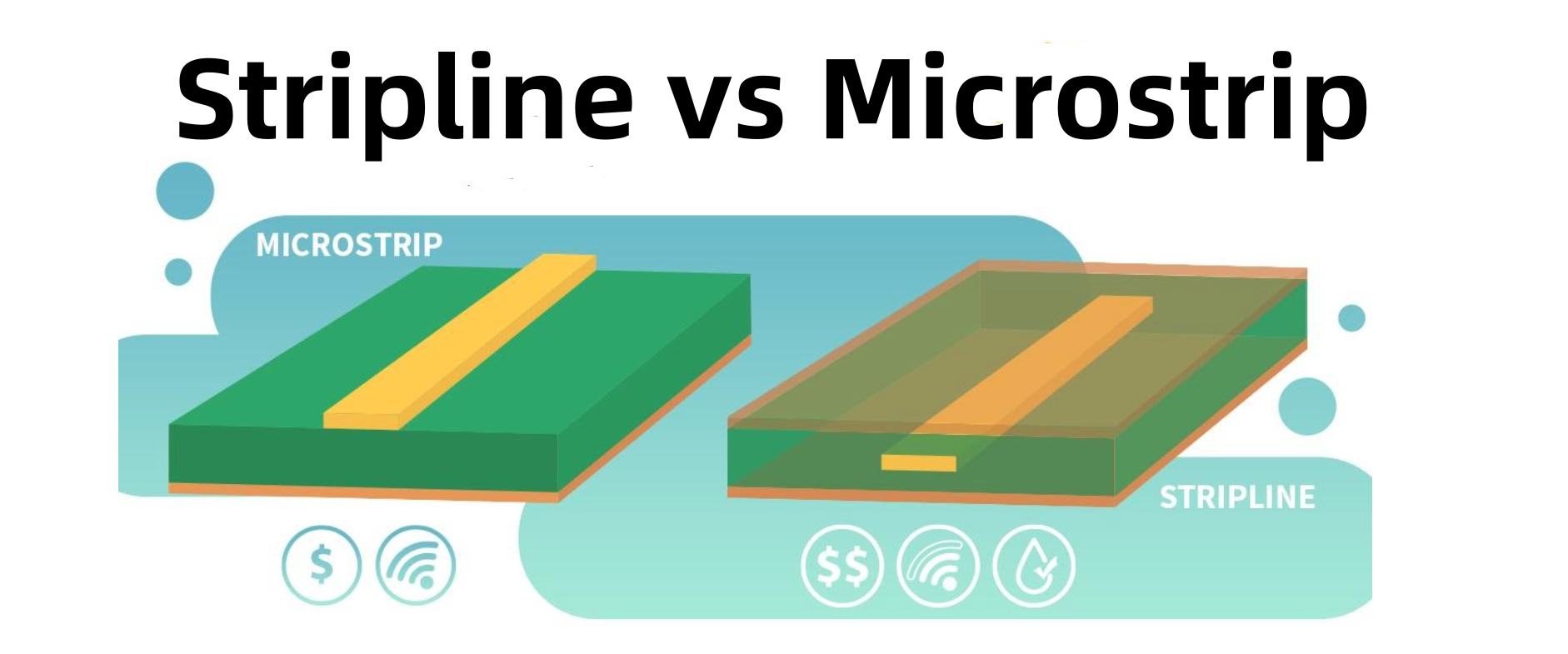
Microstrip Construction
A microstrip line consists of a single conductor trace routed over a dedicated reference ground plane across the board dielectric.
Microstrips are simple to construct requiring only standard copper layers. They avoid complex multi-layer boards.
Stripline Construction
A stripline is composed of a conductor sandwiched between two reference ground planes within internal board layers.
This creates an isolated shielded embedded signal cavity. Striplines mandate more complex multilayer board fabrication.
In summary:
| Metric | Microstrip | Stripline |
|---|---|---|
| Layers | 2+ | 4+ |
| Process Complexity | Simple | Challenging |
| Cost | Lower | Higher |
Crosstalk
Due to their exposed nature, microstrips suffer from increased vulnerability to crosstalk versus fully-shielded striplines:
Several effects contribute to microstrip crosstalk susceptibility:
- External EMI – Air serves as propagation medium from external noise sources
- Lateral coupling – Adjacent traces couple through board dielectric
- Lower impedance – Less electrical isolation from ground plane
In contrast, the encapsulated stripline construct shields against external interference sources leading to much higher isolation:
Losses
Beyond susceptibility, striplines also demonstrate lower loss tangents:
Microstrips suffer from conduction losses into the board dielectric whereas striplines confine fields between ground planes:
| Loss Mechanism | Microstrip | Stripline |
|---|---|---|
| Conductor Losses | High | Low |
| Dielectric Losses | High | Low |
This enables striplines to support longer route lengths and/or higher signal frequencies.
Modeling and Analysis
The interactions between the trace, reference plane(s), boards dielectrics, and air boundary conditions determines transmission line behavior:
- Characteristic impedance
- Effective dielectric
- Phase delay
- Loss tangent
And in turn the ability to transmit signals with acceptable fidelity and interference at target data rates.
Modeling striplines leverages classical closed-form 2D electrostatic and magnetostatic mathematics applied symmetrically between reference planes:
Conversely, microstrips feature a more complex asymmetric open-boundary problem requiring sophisticated 3D electromagnetic field modeling:
This impedes achieving comparable accuracy without extensive numerical simulation. Even with modern solvers, microstrip analysis involves greater abstraction and approximations.
Signal Integrity

Given the combined effects of easier modeling, better shielding, and lower losses, striplines deliver superior overall signal integrity essential for multi-gigabit signaling:
By mitigating interference and distortion, excellent eye patterns and timing margins are preserved at high frequencies across longer stripline channels.
Conversely microstrips exhibit worse case eye closure and jitter:
Routing Considerations for High Speed Signals
Due to their performance edge for signal integrity, striplines constitute the preferred transmission line for routing high speed lanes like PCIe, USB 3.0, Ethernet etc:
However for cost or layer count constrained designs, microstrip may work given modest data rate requirements.
Always first prototype prospective signal carrying microstrips to validate acceptable performance. Leverage smaller pad sizes, routing adjacency avoidance, shield cutouts, and crosshatch ground fills to optimize SI where possible. But recognize microstrip limitations on achievable loss and interference rejection.
For more moderate bandwidth interfaces with flexible SI tolerance and board simplicity needs, microstrips suffice. But mission critical high speed links demand properly implemented striplines to reliably attain multi-GBps throughput.
Example Applications
Microstrips – Cost-driven boards, modest data rates, low quantity prototypes
Striplines – High volume product, signal integrity essential, performance critical
Some representative use cases:
| Application | Microstrip | Stripline |
|---|---|---|
| Hobbyist Arduino interface | ✅ | |
| Multi-Hundred GBps datacenter switch | ✅ | |
| Spacecraft command/control system | ✅ | |
| Low-cost IoT sensor hub | ✅ | |
| Automotive drive recorder | ✅ |
Matching transmission line variety to product needs ensures optimizing cost, complexity and signal fidelity.
Conclusion

In summary, while microstrips and striplines share seemingly analogous roles for intra-board connectivity, their salient distinctions drive suited applicability:
Microstrips – Lower complexity and cost but with signal integrity limitations
Striplines – Superior performance yet demanding intricate multilayer boards
Carefully weigh tradeoffs like fabrication budgets, layer constraints, acceptable loss and interference levels, production volume and other aspects. There exist reasonable use cases for both approaches, but take care selecting wisely! Mistakes lead to SI debugging nightmares or unnecessary expense for commodity applications alike. A keen understanding of electrical constraints greatly eases navigating design decisions between these two popular transmission line structures.
Frequently Asked Questions
Q: Which provides lower loss for high frequency applications – microstrips or striplines?
A: Striplines overwhelmingly demonstrate lower loss tangents given superior field confinement between ground planes. Microstrips suffer from dielectric interaction leading to greater attenuation at high frequencies or long trace lengths.
Q: How do fabrication cost differences between microstrips vs striplines impact very high volume production?
A: Complex multilayer boards with higher layer counts impose a fixed cost penalty, but negligible incremental price per additional unit. So above breakeven points, total cost of striplines can drop below cheaper microstrip boards given reduced rework, scrap, and testing expense for the more robust designs.
Q: What construction approaches help mitigate microstrip susceptibility to EMI and crosstalk?
A: Added shielding planes adjacent to microstrips, strategic ground stitching vias isolating lanes, routing over solid ground planes, and differential pairs help strengthen isolation and interference rejection. But inherent limitations still exist.
Q: Can microcontrollers using moderate speed parallel buses leverage microstrips safely?
A: Yes, given simpler non-serial bus formats, relaxed timing margins, modest data rates below ~50-100Mbps, and finite short trace lengths, microstrips work sufficiently to carry control and data channels for many embedded applications without needing complex stacks.
Q: What emerging technologies aim to compete with striplines for high density low loss routing?
A: Embedded multi-layer organic substrates and 3D integration leveraging through silicon vias (TSVs) offer potential paths to achieve stripline-class performance using novel architectures to circumvent fabricated multilayer drawbacks like lamination thickness. But these bring respective cost and interconnect reliability challenges.


