Surface mount technology (SMT) refers to the method of mounting electronic components directly onto the surface of a printed circuit board (PCB) without through-hole leads. Instead, surface mount components have terminations that solder directly to flat copper pads on the outer surfaces of the PCB.
SMT transformed electronics manufacturing by enabling smaller, faster, and lower cost circuit assembly compared to older through-hole mounting. This article provides an in-depth overview of surface mount technology including:
History of Surface Mount Technology
- Origins in the 1960s electronics industry
- Gradual adoption over through-hole mounting through the 1970s-80s
- Wider industry acceptance since widespread automation in the 1990s
- Now the dominant approach for high-volume PCB assembly
Benefits of SMT Components
- Smaller size than through-hole parts
- Assembly automation and speed
- Higher component density on circuit boards
- Improved reliability with fewer solder joints
- Easier rework of defective components
- Flexible circuit board design
Types of SMT Components
- Passive parts like resistors, capacitors, and inductors
- Integrated circuits like processors, memory, and logic chips
- Connectors, sockets, switches, and other electromechanical parts
SMT Manufacturing Processes
- High-speed component placement machines
- Reflow soldering ovens
- Automated optical inspection (AOI)
- Selective wave soldering
- Rework stations
SMT Design Considerations
- Component footprint layout
- Thermal management
- Manufacturing tolerances
- Inspectability and testability
Surface mount technology now dominates electronics manufacturing, enabling more compact and advanced circuit board designs across all types of devices and industries.
History and Origins of Surface Mount Technology
The origins of surface mount technology trace back to the 1960s when the electronics industry sought new assembly methods to build smaller, lighter, and faster circuitry.
Motivations for Developing SMT
Several factors drove interest in alternatives to conventional through-hole component mounting:
- Miniaturization needs as transistors and integrated circuits shrank
- Circuit complexity growing beyond through-hole density limits
- Eliminating manual insertion and soldering to enable automation
- Faster electrical performance from shorter connections
- Reducing costs through optimized production
Early SMT Development
Key milestones in pioneering surface mount technology:
- 1961 – Fairchild Semiconductor attaches bare dice directly onto boards to eliminate packaging and wires.
- 1964 – IBM solders disk-shaped parts onto ceramic boards in an early SMT approach.
- Late 1960s – Welded titanium pins enable automated component attachment to boards.
- 1970 – Chip carrier packages introduced, allowing solderable leads.
These initial concepts established the possibility of automated component mounting without wire leads or axial terminations.
SMT Commercialization and Growth
Surface mount technology gained broad industry adoption by the 1980s:
- Improved masking and solder creams enabled reliable SMT solder joints.
- Pick and place machines could quickly mount SMT components onto boards.
- SMT assembly lines increased throughput rates by 5-10x over through-hole.
- Variety of leaded and leadless SMT component packages offered.
- Cost reductions drove high-volume manufacturers to switch to SMT.
While some through-hole components persist, SMT came to dominate electronics manufacturing by the 1990s and remains ubiquitous today.
Benefits of Surface Mount Technology
Surface mount technology provides multiple advantages over traditional through-hole PCB assembly:
Size Reduction
SMT components occupy much less circuit board area since they do not require clearance for wire leads to pass through holes. The footprints are typically >70% smaller.
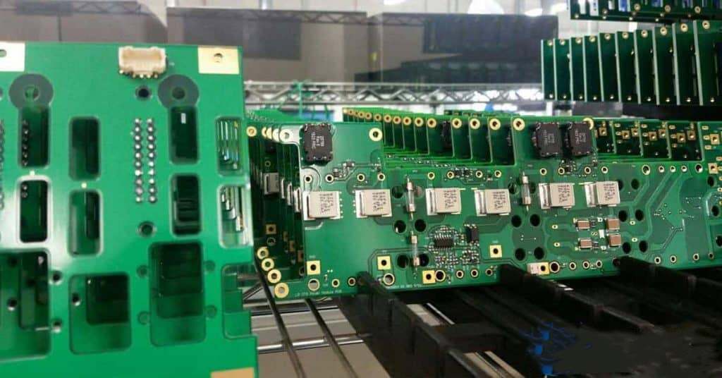
Component Density
Eliminating through-holes allows packing more surface mount components in the same board space. SMT may achieve 5-10x greater component density compared to an equivalent through-hole design.
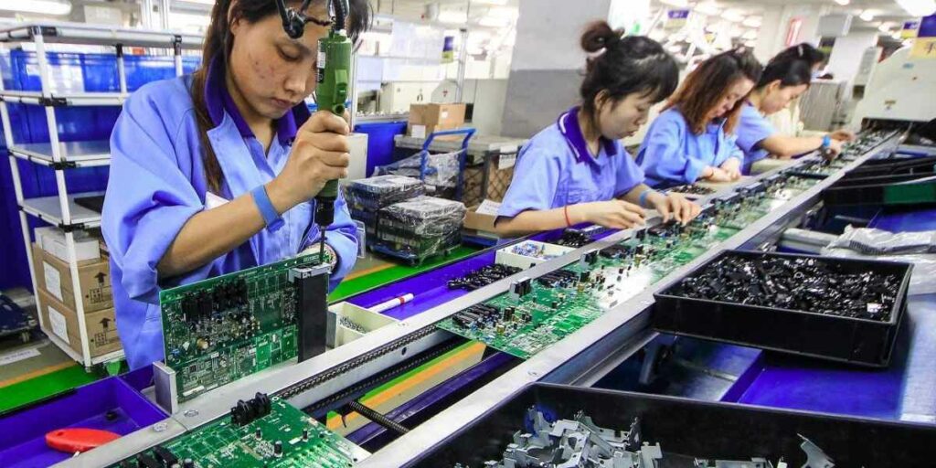
Automated Assembly
SMT parts lend themselves to automated pick-and-place assembly, enabling mass production. Through-hole assembly remains manual.
Simplicity
Surface mounting requires only a single solder joint per termination. Through-hole leads require two joints per lead or pin.
Reliability
The single solder joints per lead in SMT are more reliable than dual joints prone to fractures. SMT avoids bent wire leads too.
Design Flexibility
Without through-holes dictating layout, SMT allows more PCB routing flexibility for compact, high-performance designs.
Reworkability
Blowing hot air on SMT joints allows easy rework of defective parts. Through-hole rework requires desoldering all leads.
Speed
Shorter conductive paths from SMTs increase signal speeds and high-frequency performance.
The small size, automation-friendly assembly, and reliability make SMT ideal for modern electronics manufacturing.
Types of Surface Mount Components
Many types of electronic components are available in surface mount packages suitable for SMT assembly:
Passive Components
- Resistors – Thick film, thin film, chip arrays, and power surface mount resistors. 0201 and 0402 sizes common.
- Capacitors – Stacked ceramic multilayer, tantalum, film, chip and other capacitor dielectrics offered in SMT.
- Inductors – Small surface mount coils and transformers with ferrite or air core designs.
Active Components
- Integrated Circuits – SMT package styles like QFP, SOP, QFN, BGA and CSP for ICs of all complexities.
- Transistors and Diodes – SOT-23 and SOD-123 common SMT transistors and diode packages.
Electromechanical Parts
- Connectors – SMT headers, edge card sockets, USB, D-Sub, modular jacks and other connectors.
- Switches – Tactile switches, DIP switches, slide switches with SMT pins.
- Relays – Lower-power reed relays or solid state relays with SMT terminations.
- Crystals – Clock oscillators and resonators in surface mount cans.
Almost any electronic part can now be found in a surface mount-compatible package suitable for SMT assembly.
SMT Manufacturing Processes
Specialized equipment and processes used in SMT manufacturing include:
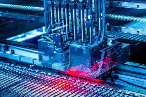
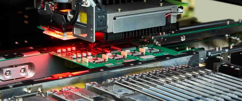
Pick and Place Machines
These assembly robots precisely pick components from reels or trays and place them onto PCBs. Sophisticated vision alignment and high-speed capabilities allow accurate, rapid placement.
Solder Paste Printing
Solder paste containing powdered solder and flux is printed onto pads through stencils before component placement. Allows precise depositing.
Reflow Soldering
PCBs with solder paste and components pass through a reflow oven using heat to melt the solder paste and attach parts.
Wave Soldering
Selective wave soldering machines pass just the underside of a PCB over a waves of molten solder to solder through-hole parts and pins.
Automated Optical Inspection (AOI)
Cameras image the assembled PCBs and use software algorithms to check for missing, misaligned or defective components.
Rework Stations
Hot air tools remove and replace defective surface mount parts without damaging PCBs or adjacent components.
SMT lines utilize these technologies for high-volume, reliable, inspected production runs manufacturing PCB assemblies.
SMT Design Considerations
Several factors must be addressed when designing boards for surface mount assembly:
Component Footprints
The copper pad shapes and sizes must match the leads of the surface mount components to ensure accurate placement.
Thermal Management
SMT parts produce heat needing dissipation. Thermal vias, pads, and planes help conduct heat to avoid temperature rise.
Manufacturing Tolerances
Designs account for pick-and-place placement precision, solder mask alignment, and other tolerances to ensure manufacturability.
Inspectability
Keep components far enough apart for cameras to image them clearly. Provide fiducials for optical alignment.
Test Points
Include vias and test lands for probing circuits. SMTs obstruct access requiring creative test point arrangements.
Thermal Cycling
Match component and board thermal expansion characteristics to avoid solder joint stresses over temperature cycles.
With careful design considerations, surface mount technology allows creating high-density, optimized, reliable PCB assemblies cost-effectively.
Conclusion
Surface mount technology transformed circuit board fabrication and assembly by enabling miniaturized, automated manufacturing with improved reliability. After early efforts in the 1960s, SMT gained widespread adoption by the 1990s and now dominates modern electronics assembly lines thanks to the small component sizes, automation-friendly process, and flexibility it provides. SMT will continue advancing PCB capabilities into the future.
Surface Mount Technology FAQ
When was surface mount technology first introduced?
The precursor concepts trace back to the 1960s, but surface mount did not gain broad commercial adoption until the 1980s and 90s with advances in packaging, soldering, and assembly automation.
What are the main benefits of SMT over through-hole mounting?
Greater component density, smaller size, automated assembly, simplicity of solder joints, improved reliability, design flexibility, easier reworkability, and superior electrical performance.
What types of components are available as SMT packages?
Almost all types, including passives like resistors and capacitors, active ICs, transistors, diodes, connectors, sockets, switches, oscillators, filters, ferrite cores, and various other electromechanical components.
What is the key soldering technology used in SMT assembly?
Reflow soldering ovens pass circuit boards with applied solder paste and components through heat zones to melt the paste and attach parts. It enables mass soldering.
How does one fix defective SMT components?
Specialised rework stations use hot air jets to locally heat solder joints and remove components for replacement without damaging nearby parts. Makes repair easier than soldering multi-lead through-hole parts.


