Introduction
Mounting refers to the process of securing printed circuit boards (PCBs) in their enclosures and installing them into systems or assemblies. Proper mounting is essential for mechanical stability, thermal management, safety, and reliability.
This comprehensive guide covers key aspects of PCB mounting including:
- Mounting methods like screw, standoff, tray, wedge
- Mounting hardware such as spacers, standoffs, brackets
- Thermal considerations for heat dissipation
- Shock and vibration absorption techniques
- PCB stiffening and reinforcement options
- Best practices for robust mounting
- Mounting in challenging environments
- Innovations in mounting technology
Understanding PCB mounting principles empowers designers and integrators to deploy boards successfully in demanding real-world operating environments.
Why is Proper PCB Mounting Important?

Adequately mounting PCBs is critical because:
- Prevents Damage: Secures boards firmly to prevent damage due to shock, vibration, and flexing during usage as well as handling.
- Enables Cooling: Allows heat transfer from components to enclosure for effective cooling.
- Provides Reliability: Stops boards from shifting so solder joints and connectors do not fatigue over long term.
- Ensures Safety: Stops accidental contact with high voltages on boards through proper enclosure design.
- Allows Accessibility: For ease of servicing, upgrade and board removal.
- Meets Standards: Certain mounting methods mandated for regulatory or environmental compliance.
- Reduces Noise: Prevents issues like electromagnetic interference by grounding boards.
- Optimizes Function: Ideal board placement, alignment and orientation ensures correct operation.
In short, proper mounting directly impacts the product lifetime, safety, and performance – making it a vital mechanical design consideration.
PCB Mounting Methods
There are several standard techniques and hardware options for mounting PCBs:
Screws
- Most common mounting method
- Screws pass through holes in PCB into standoffs/bosses in enclosure
- Allows easy installation and removal
- Screw type (machine, self-tapping) and size depends on application
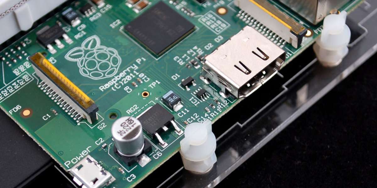
Spacers and Standoffs
- Standoffs are threaded pillars to distance PCB from enclosure
- Provides secure mounting and thermal isolation if needed
- Spacers used to stack multiple boards
- Made of nylon, aluminum etc.
Card Guides and slots
- Boards slid into slots milled into the enclosure
- Grooves keep board aligned and densely packed
- Allows easy insertion and removal if positioned correctly
Wedge Mounting
- Boards press-fit at an angle into slotted card guides
- Friction holds board in place
- Common in high vibration environments like vehicles
Snap-fit Mounting
- Boards slide and lock into place with tabs or fasteners
- Tool-less installation but may require higher insertion forces
Adhesive Mounting
- PCB bonded directly to enclosure surface with adhesive
- Affords installation flexibility and damping
- Permanent mounting complicates repairs
Tray Mounting
- Boards are placed into punched metal trays
- Trays typically slide into shelf/rack assembly
- Provides organization and modularity
The optimal method depends on mechanical design factors, required access, operating conditions, and cost targets. A combination of techniques may be required.
Thermal Considerations for Mounting
Careful mounting design is key for transferring heat from components to avoid overheating:
- Use thermally conductive standoff materials like aluminum alloy
- Avoid nylon standoffs for high power boards
- Position boards for shortest path to enclosure cooling features
- Maximum contact between board and chassis improves heat transfer
- Use of thermal pads or grease enhances thermal interface
- Mounting screws can act as heat sink fasteners for hot components
- Cutouts above components may be needed for airflow
- Tall components may require clearance holes in enclosure
- Minimize layer count between hot components and ground plane
Thermal analysis early on guides design of required heat dissipation mounting provisions.
Managing Vibration and Shock
For applications involving vibration and shock, the mounting solution must isolate and protect the PCBs:
- Snubbers – rubber mounts to dampen vibrations
- Grommets around mounting holes to absorb shock
- Cushioned card guides instead of rigid slots
- Vibration rated connectors with positive locking
- Avoid hollow standoffs prone to amplification
- Conformal coating provides moisture and mechanical protection
- Avoid heavy heat sinks that can transmit shock
- Potting highly sensitive boards reduces motion
- Care with board orientation to avoid resonance frequencies
- FEA analysis informs vibration isolation needs
Tailored mounting techniques coupled with board level strengthening curtails damage in harsh environments.
Techniques for Stiffening and Reinforcing PCBs

To withstand high mechanical stresses, PCBs themselves can be reinforced:
Stiffeners
- Ribs or beams bonded to the board surface
- Adds stiffness against bending and flexing forces
- Located strategically based on FEA analysis
PCB Thickness
- Specifying thicker copper layers resists flexing
- Multilayer board inherently stiffer than double sided
Additional Layers
- More internal copper layers makes board more rigid
- But increases cost, via drilling complexity
Specialty Substrates
- Metal core PCBs offer enhanced structural rigidity
- PTFE substrates maintains stability under temperature swings
Conformal Coating
- Coatings like acrylic, urethane, silicone seal boards
- Increases resistance to vibration, moisture, chemicals
Corner Bracing
- Triangle corner brace on perpendicular edge
- Reduces corner stress concentration
Component Bonding
- Gluing critical components prevents cracking solder joints
- Socketing tall ICs can reduce stresses
A structured approach to board reinforcement and protective measures enables rugged performance.
Best Practices for Robust PCB Mounting
Follow these guidelines to implement reliable mounting:
- Start planning early during the design phase based on enclosure dimensions
- Size and position mounting holes for easiest access
- Ensure mounting holes are properly drilled and plated
- Account for board tolerances and allow clearances
- Use spacers if tight clearances to prevent shorts
- Include corner support for large boards
- Evaluate shock, vibration specs to guide isolation needs
- Specify torque for mounting hardware to prevent damage
- Assess component height restrictions and heat dissipation
- Review options to maximize thermal transfer to enclosure
- Plan straight and secure connector placements
- Analyze effects of differential thermal expansion
- Consider ease of board installation and removal
- Examine consequences of failure with FMEA
- Test mounted board prior to production release
Careful attention to mounting considerations early in the design flow prevents headaches later when deploying boards in the field.
Mounting PCBs in Challenging Environments
In extreme environments, PCB mounting requires additional provisions:
Outdoor Enclosures
- Use conformal coating, potting for moisture protection
- Avoid hollow standoffs prone to condensation
- Prevent water ingress with seals, filters, drain holes
- account for solar heating, temperature swings
Mobile Mounting
- Manage shock, vibration and extreme temperatures
- Wedge locks, card cages, and board stiffening techniques
- Avoid heavy heat sinks adding mass
Harsh Industrial Environments
- Meet NEMA ratings for sealing, corrosion, haz-loc protection
- Secure components against intense vibration
- Withstand wide temperature ranges and thermal shock
High Reliability Applications
- Implement redundancy with dual mounted boards -HESIORanalysis guides structural reinforcements
- Follow rigorous installation and maintenance procedures
EMI/EMC Shielding
- Use conductive gaskets at enclosure interfaces
- Proper grounding, filtering and isolation
- Specialty shielded connectors
The right combination of mounting provisions tailored to the operating environment enables reliable functioning even under punishing real-world conditions.
Innovations in PCB Mounting Approaches
PCB mounting continues to advance with new techniques and hardware:
- Vibration isolation mounts – patented enclosures with active cancellation of resonant frequencies using feedback control techniques. Allows operation of sensitive boards in highly dynamic environments.
- Liquid cooling mounting plates – Directly mounted cold plates maintaining boards at controlled temperatures while transferring heat to remote radiators for demanding applications.
- Tuned mounts – Custom mounts that attenuate specific vibration frequency ranges based on application dynamics.
- Composite board materials – Metal composite PCB substrates that offer enhanced thermal conductivity, dimensional stability across temperature, and structural rigidity to prevent flexing.
- Direct bonding – Techniques to directly bond bare boards to finished aluminum frames and enclosures while achieving electrical isolation. Improves thermal transfer while eliminating traditional mounting hardware.
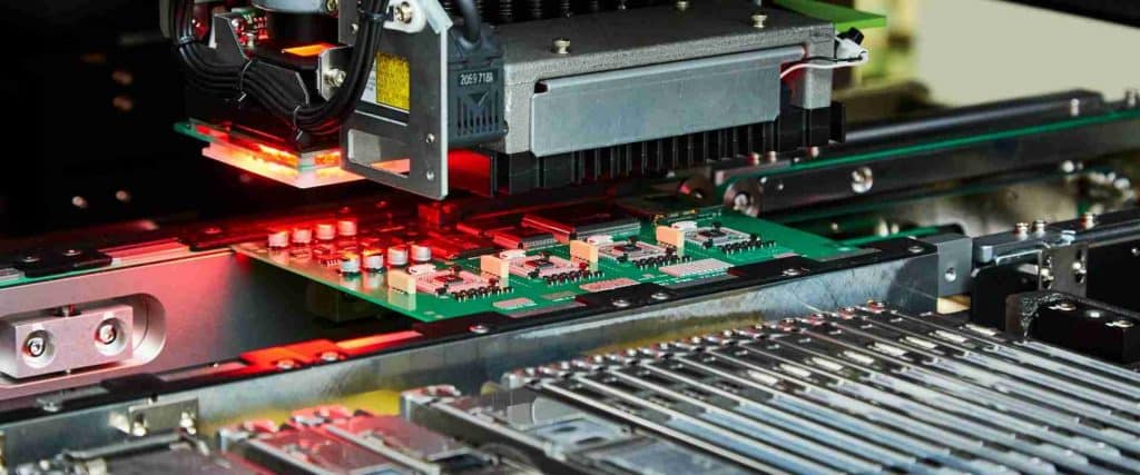
- Automated insertion/extraction – Robotic mechanisms to automatically install and remove boards from chassis and backplanes without human intervention.
These enhancements expand the operating envelopes for advanced electronics in cutting edge applications.
Conclusion
Adequate mounting is a vital mechanical design step that directly impacts the reliability, safety, and performance over the product lifetime. A variety of mounting techniques and hardware allow securing PCBs inside enclosures and equipment in a way that meets mechanical, thermal, and access needs.
Careful design analysis coupled with testing helps implement rugged mounting solutions able to survive real-world conditions. As electronics shrink in size but grow in power, innovative mounting methods that manage vibration, shock, and heat will remain essential for enabling next generation products.
Frequently Asked Questions
Here are some common questions on PCB mounting answered:
Q: Why is proper PCB mounting important?
A: Good mounting prevents damage, enables cooling, ensures reliability and safety, allows servicing, meets regulatory standards and reduces noise.
Q: What are some common PCB mounting methods?
A: Screws, spacers, card guides, wedge mounting, snap-fit, adhesive, and tray mounting are commonly used techniques.
Q: How is vibration managed in mounted PCBs?
A: Using dampers, grommets, cushioned cards, vibration-rated connectors, conformal coating, potting, FEA analysis, and orientation control.
Q: What are some ways PCBs can be reinforced structurally?
A: Adding stiffeners, using thicker cores, extra layers, metal core or PTFE substrates, corner bracing, component bonding.
Q: What innovations are emerging in PCB mounting technology?
A: Vibration isolation mounts, liquid cooling plates, tuned mounts, metal composite PCBs, direct bonding, and automated insertion/extraction.


