Reflow soldering refers to a process used to form electrical interconnections between component leads or pads on a printed circuit board (PCB) by applying solder alone without additional hand soldering.
In reflow, solder paste containing powdered solder alloy and flux is first screen printed or dispensed onto pads. Components are then placed, and the entire assembly is put through a temperature profile in a reflow oven causing the solder to melt, flow, and solidify once cooled to form permanent solder joints.
This process enables quality, high-volume surface-mount device soldering critical for modern electronics assembly vs tedious manual soldering. Reflow methods, equipment considerations, solder materials, profile optimiztions, and defect troubleshooting are examined.
Evolution of Reflow Soldering
Reflow transformed electronics assembly by reducing manual effort and enabling reliable attachment of complex components like fine-pitched integrated circuits or bottom-terminated devices unachievable by hand:
Wave Soldering Origins
Early surface mount techniques like wave soldering passed boards over flowing pumped solder, but only worked for one-sided components with bottom contacts. Tedious glue or securing was required to temporarily hold tiny or multi-terminal parts in place.
Manual & Dual Flow Methods
Pick-and-place machines allowed positioning SMD parts precisely but operators still manually touched soldering irons or dual-flow machines to tack devices before additional oven passes, slowing throughput with substantial labor costs associated.
Infrared Reflow Concept
The concept of using precisely contolled ovens to uniformly preheat PCBs to activate integral solder paste melt avoided supplemental hand work and increased penetration into fine pitch crevices, trouching off revolution.
Optimization & Automation
Reflow process refinements like profile smoothing, nitrogen atmospheres, advanced optical inspection, and integration with pick-and-place sequencers established reflow soldering as defacto methodology for volume SMD production driving double digit CAGR growth rates forecasted ongoing.
In 2023, virtually all high tech consumer products contain components applied vi reflow in smooth, lights-out operations enabling ongoing gadget and solution miniaturizations we now take for granted.
Solder Paste Basics
Reflow soldering utilizes solder paste – a viscous material consisting of suspend spheroidal alloys powder incorporatng flux additives – dispensed onto PCB copper pads in controlled volumes before component placement.
During temperature exposure, the paste ingredients interact to produce quality solder joints determined by specific composition characteristics:
Alloy Powder
Tin-lead and lead-free alloys using metals like tin, silver, copper demonstrate desired melting behavior, wetting dynamics, mechanical properties, and conductivity for electronics connections once reflowed.
Flux Agents
Fluxing additives in paste aid wetting during reflow by removing surface oxidation layers through gentle acidic reaction while preventing re-oxidation of hot molten metals through heat exposure until cooled.
Rheological Factors
Characteristic viscosity, slump resistance, tack retention, and other rheological factors govern dispensability and acquiesce of paste across varied board/stencil geometries between print and reflow stages. These properties can tuned.
Particle Size
Smaller powder spheres improve coalescence and melting fluidity while larger particles can overexpression defects like solder balling. Typical sizes range from 25-45 microns based on alloy and pitch tightness.
Performance tradeoffs tied to the above interdependent paste properties determines assembly suitability for particular components and PCB designs driving extensive characterization and process refinements by solder material suppliers during formulation.
| Paste Property | Significance | Tuning Method |
|---|---|---|
| Powder Melting Point | Solidus/liquidus reflow temperature targets | Alloy ratios adjustment |
| Flux Activity | Oxide removal vs residue levels | Flux chemistry modulation of acid components |
| Viscosity/Tackiness | Print transfer efficiency, slump resistance | Mix variances, polymer rheological additives |
| Metal Content | Post-reflow joint alloy residual | Powder density setpoints |
| Powder Size Distribution | Fluid dynamics, coalescence, self-alignment | Controlled milling processes |
Table: Key solder paste formulation characteristics
Reflow Process Overview
The reflow process consists of the following primary stages to transform solder paste deposits into metallurgical component bonds:
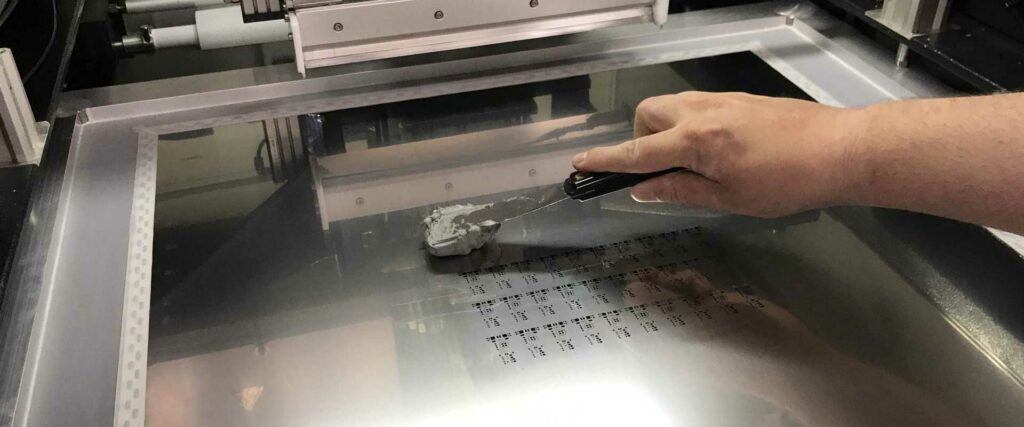
Print Deposition
Solder paste gets precisely deposited onto target pad areas through stencils using squeegee screening or jet/extrusion dispensing tools.
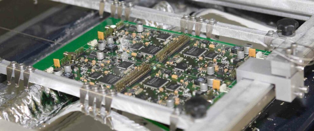
Component Placement
Robotic pick-and-place machines position surface mount parts onto applicable paste pads using programmed fiducials and angle orientation.
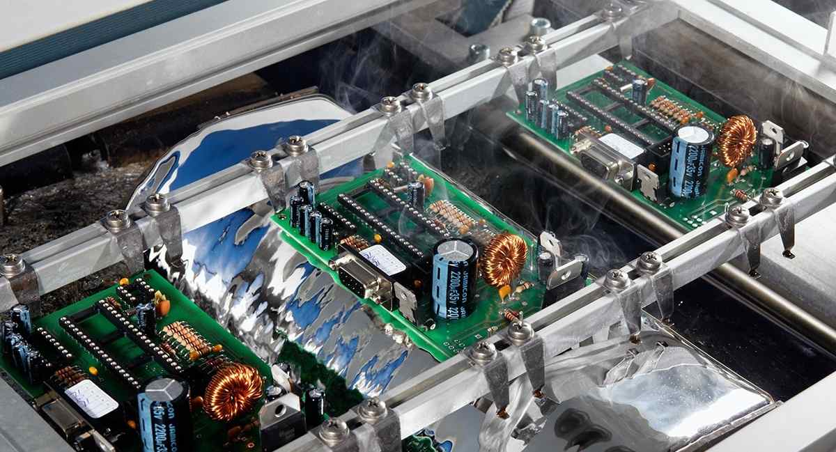
Reflow Exposure
Ovens with segmented thermal zones generate required time-temperature reflow profile shape to activate paste melting, wetting, and solidification dynamics while transporting PCBs between zones on conveyors.
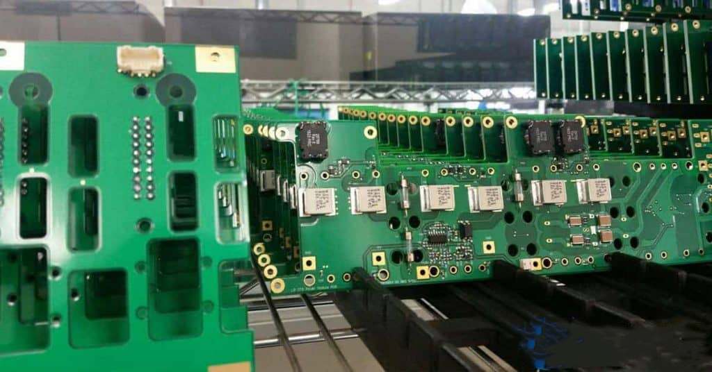
Inspection
Automated optical systems capture images of reflowed solder joints analyzing for acceptable fillet shapes, alignments, and common defects prior to downstream processes.
When executed properly, the coordinated sequence reliably attaches components to boards using only solder alloy without risks or delays of manual soldering even for ultra fine pitch devices.
| Stage | Purpose | Common Methods | Key Metrics |
|---|---|---|---|
| Print Deposition | Dispense paste onto pads | Stencil screen, jetting | Print registration, volume, slump |
| Component Placement | Position parts on paste | Pick-and-place machine | Accuracy, rotation, force |
| Reflow Exposure | Heat to melt then solidify paste | Conveyor oven, targeted IR | Temperature profile – time above liquidus |
| Inspection | Validate joint cohesiveness | AOI machine vision | Fillet presence, tombstoning |
Table: Overview of key stages in typical reflow solder process workflow
Solder Paste Printing
Applying solder paste accurately onto boards marks first critical phase of reflow process using either stencil screening approaches or jetting technology:
Stencil Screen Printing
Metal foil stencils containing laser cut apertures matching PCB layouts get mounted onto tooling frames in printers allowing controlled squeegee blade passages to force paste through openings onto boards below in precise registration and depth.
Stencil processes can rapidly print complex board areas but rely on frequent cleaning cycles to maintain aperture clarity plus stencil maintenance/changeovers between designs. Registration also challenges certain density layouts.
Jet/Extrusion Dispensing
Alternatively, programmable jet valves directly propel pressurized paste droplets onto pads based on software pattern generation while extrusion tools force deposition through needle tip nozzles trailing boards in x/y raster motion.
Though slower than foil screening, no physical templates makes job changeovers cleaner without aperture upkeep while flexibly addressing hard-to-print regions, allowing just-in-time printing. Hybrid machines combining stencil and jet now enable selecting best approach area by area.
| Method | Advantages | Limitations |
|---|---|---|
| Stencil Screen | High speed, low cost for production | Regular cleaning cycles, changeovers |
| Solder Jet Printing | No stencils, flexible small jobs | Currently slower, lower deposit heights |
| Solder Extrusion Printing | Handles challenging geometries | Limited speed, higher machine costs |
Table: Comparison of common solder paste printing approaches
Pick and Place Assembly
Once solder paste gets printed onto boards, robotic pick-and-place systems populate components onto applicable pads by actively manipulating parts fed from reels, trays, tapes and other integrateable feeders guided by software job creation processing input data from multiple sources:
Bill of Materials & Parts Library
Reference database details component dimensions, weights, terminal configs, packing media formats, feeder mappings, and other attributes for targeted device variety set supporting given assembly.
PCB Data Files & Images
CAD export contains board profiles, target location info, and paste layer images to calculate positioning targets while compensating for thermal expansions or trim distortions relative to static fiducial alignments.
Feeder Setup Records
Machine integrates appropriate component reel sizes, slot assignments, and calibrated offset tweaks to synchronize final placements suiting presented parts inventory physically provisioned.
Vision & Metrology
Camera reads paste deposits or panel fiducials for adaptative alignment then measures actual parts from feeders comparing against libraries to refine gripping points before final calculated motion execution and termination sensing.
By fusing preparations, calibration, and real time feedback at component level, pick-and-place automation achieves assembly accuracies measured in hundreds of microns enabling scalable microelectronics fabrication essential for driving IT industries forward.
| Function | Parameters | Tolerances | Inspection |
|---|---|---|---|
| Target Information | Location, device orientation | +/- 100 μm | Optical alignment |
| Part Gripping | Nozzle style, vacuum pressure | Height +/- 50 μm | Pre-pick validation |
| Placement Force | Grams per terminal, impact energy | 10-250gf | Post-drop detection |
| Termination Sensing | Dwell durations, nozzle current | 1-50 ms | Bondline imaging |
Table: Overview of key pick-and-place steps and typical capability range
Solder Reflow Methods
In order to actuate state transformations in dispensed solder paste activating intermetallic bonding formation, thermal reflow exposure gets applied through inline oven conveyance utilyzing different heating methods suitable for volume production environments:
Convection Reflow
Forced impinged air heaters combine with underlying thermoconduction plates progressing boards through multiple temperature zones approximating ideal reflow profile curve shape targeting peak above 217°C achieving coordinated melting followed by controlled cool down.
While effective for typical assemblies, large board sizes or high density areas can suffer inconsistent outcomes from macro heat differentials across areas.
Vapor Phase Reflow
Alternatively, precisely controlled boiling fluorinert vapor heat transfer fluid provides very uniform wetting convection vital for minimizing stresses like package warping induced in high temperature sensitive components during soak while eliminating defects like tombstoning through favorable meniscus dynamics.
Infrared Reflow
IR emitting panels directed locally just above boards can reduce process lengths by rapidly prompting paste melt releasing parts readily from tacky flux residues once collapsed while avoiding bulk board heating provided sufficient profiling exists between zones preventing offsets or precursor slumping ahead of target regions.
Laser Assisted Reflow
Supplemental zone targeted high energy lasers sharpen profiles in confined regions of interest with precision impossible through external heating that might disturb neighboring locales helpful for chip scale or embedded joining requirements.
In all cases, monitoring temperature exposure of paste above liquidus and time about solidus thresholds while carefully managing ramp differentials proves vital to gain sound assemblies.
| Approach | Heat Source | Strengths | Weaknesses |
|---|---|---|---|
| Convection | Forced hot air heaters | Balance of cost and capability for general use | Density variations across larger boards |
| Vapor Phase | Boiling fluorinert oil | Excellent uniformity ideal for chips and large boards | Limited heat capacity challenges extreme thermal densities |
| Infrared | IR emitter arrays | Very rapid selective reflow possible | Can induce secondary placement shifts around target zones |
| Laser Assist | Directed diode lasers | Precision impossible with external sources | Limited penetration and small spot size |
Table: Comparison of leading thermal methods for actuating solder reflow process
Reflow Profile Optimization
To reliably form quality solder joints during thermal reflow exposure, engineers carefully tune heating zone setpoints balancing myriad material interactions influencing interconnection integrity:
Preheat Stage
Gradual heating between 60°C to 150°C activates binder burnout and paste dehydration to avoid defects like solder balling while delaying onset of flux driven acid rises preventing excessive activity later when temperature limitations restrict cleaning potency.
Thermal Soak
Dwell between 150°C to 180°C allows gradual isothermic heating for inward heat penetration achieving homogeneous temperatures across large boards which reduces mechanical stresses like substrate or component warping that might otherwise impart placement shift, lead disconnects, or latent cracks undetected until field failures.
Reflow Peak
Above 183°C rapid acceleration drives above melt point through peak hold between 30 to 90 seconds above 217°C liquefying solder activating strong wetting flow balanced by flux protection well before excessive intermetallic growth compromises joint strength followed by quick cooling through solidification and crystallization to form solder bonds.
Cooling Curve
Careful exponential decline avoiding sudden drops prevents solder balling from residual flux ash accumulation yet quick enough to inhibit grain formation from excess precipitation hardening or flux residue cracking.
The above interactive dynamics demand smooth, gradual slope changes validated through extensive thermal profiling and trial vehicles supported by predictive modeling guiding engineers selecting ideal heating methods, zone divisions, and transport speed combinations to implement robust process windows.
Troubleshooting Reflow Defects
Despite best efforts optimizing reflow, production environments still risk various defects requiring quick identification and diagnosis through systematic logic flows:
Head-In-Pillow
Rounded shape lacking fillet angles suggests poor wetting from oxide or paste contamination preventing capillary flow impeded by less thermally conductive masses requiring profile adjustments or paste integrity inspection.
Solder Beading
Extended peaks shrinking tube width often follows tombstoning resulting from paste volume excesses or component shifts from thermal differentials or placement offset indicating print or pick-and-place review needs.
Pinholes & Voids
Reflow separation leaving internal gaps or surface divots hints at outgassing or slump blockages early before activation points revealing potential paste handling practices requiring review to rule out expired, poorly stored batches.
Cold & Disturbed Joints
Malformed grainy joints symbolize premature reflow termination likely from uneven conveyor transport stalling requiring maintenance while nearby shifted parts should increase suspicion of heater reliability.
Flux Residue
Dark staining around joints or boards correlates to residue buildup from paste chemistry mismatches to profile for a given board size and complexity suggesting manufacturer reformulation or reflow parameter changes may prove beneficial.
By methodically tracing symptoms backwards through process stages, defects point closer towards relevant mechanisms enabling corrective actions – part art, part science.
| Defect | Possible Causes | Investigation Targets |
|---|---|---|
| Head-In-Pillow | Paste contamination, oxides, insufficient heat | Profile settings, paste handling |
| Solder Beading | Excess paste, tombstoning | Print process controls, placement inspection |
| Pinholes & Voids | Flux inadequacies, outgassing | Paste storage conditions, paste formulation |
| Disturbed Joints | Non-linear heating effects | oven calibration and belt speed controls |
| Flux Residue | Excess activity, board size mismatches | Reflow parameters, paste selection |
Table: Troubleshooting suggestions for common solder reflow defects
FQA
What is the key difference between reflow soldering and wave soldering?
Reflow solders components solely using solder paste before oven heating while wave relies on flowing pumped solder contacting bottom board surfaces only. Reflow affords positioning parts on either side enabling increased density and component varieties.
Why is the cooling stage important during reflow?
Controlled cool down allows solder to solidify properly. Fast drops can readily create defects like solder balling from collapsing flux bubbles in still molten joints while slow cooling risks formation crystallization or intermetallic phases degrading strength.
What types of solder paste printing methods exist?
The two primary approaches include stencil screening forcing paste through apertures for faster complex board population and jetting/extrusion nozzle deposition avoiding stencils for greater flexibility on challenging geometries, albeit slower presently. Hybrid machines now incorporate both techniques.
How does the pick-and-place process know accurate component locations?
Combination of reference data in software libraries on device dimensions/terminals along with optical scanning of paste prints, board fiducials, and real time vision alignment of fetched parts enable precise calculated positioning meeting narrow tolerances.
Why is it important to smooth heating zone ramps during reflow?
Careful incremental zone ramping prevents rapid property changes allowing gradual reactions during flux activation, paste expansion/contraction, and wetting dynamics preventing sudden stresses leading to defects like tombstoning or beading from placement shifts and viscosity differentials.


