Introduction
Surface mount technology refers to the process of mounting and soldering electronic components onto the surface of printed circuit boards (PCBs). This process has largely replaced the older through-hole technology and now dominates modern PCB assembly.
This article provides an in-depth look at the surface mount process including:
- Advantages over through-hole assembly
- Surface mount components
- SMT equipment
- SMT process steps
- Inspection and testing
- Rework and repair
- Industry standards
Understanding the entire surface mount assembly process is key knowledge for PCB designers, electronics engineers, and manufacturing teams.
Comparison to Through-Hole Assembly
Before surface mount technology, electronic components were attached to PCBs using through-hole assembly. This involved inserting component leads into holes in the board and soldering leads on the opposite side.
While through-hole assembly was the standard for decades, surface mount offers a number of important advantages:
- Smaller components and tighter spacing – increased component density
- Assembly on just one side of the board
- Improved reliability from shorter lead lengths
- Reduced assembly costs
- Automated assembly and inspection
- Support for high I/O devices like BGAs
The transition from through-hole to surface mount assembly began in the 1980s and is now essentially complete, particularly for high volume manufacturing. Only some very large components like connectors and transformers still utilize through-hole assembly.
Surface Mount Components
A wide variety of component types and packages have been developed to support surface mount assembly:
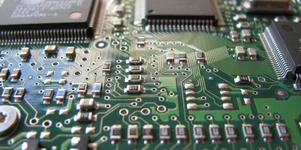
Passive Components
- Resistors and capacitors – Typically rectangular with terminals on two sides. Common packages are 0201, 0402, 0603, and larger. Materials may be ceramic, plastic, or tantalum.
- Inductors – Wound coils that come in small surface mount packages. Some are molded while others are bare windings.
Active Components
- ICs – Integrated circuits with packages designed for surface mount. This includes SOT-23, SOIC, TSSOP, QFN, BGA packages and more.
- Discrete Semiconductors – Diodes, transistors, and other discrete semiconductors come in surface mount packages like SOT-23 and SOD-323.
Other Components
- Connectors – Board-edge, circular, card edge, power, RF, and other connectors designed for SMT.
- Crystals and oscillators – For frequency references and clock generation, available as surface mount devices.
- LEDs – Light emitting diodes come in specialized SMT packages to fit pick and place equipment.
- Thermal solutions – Heat sinks, thermal pads aid cooling of surface mount components.
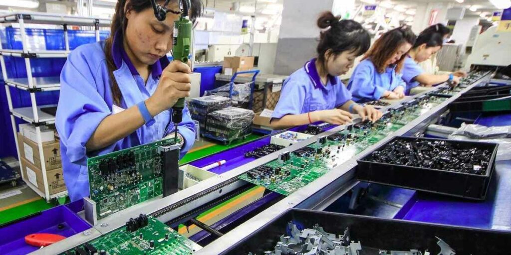
SMT Assembly Equipment
Automated equipment is essential for high volume SMT manufacturing. Typical SMT assembly machines include:
Printers
- Use a stencil to apply a precise pattern of solder paste onto pads on the PCB.
- High precision alignment of stencil to PCB is critical.
- Common printer types are fully automatic, semi-automatic, and manual printers.
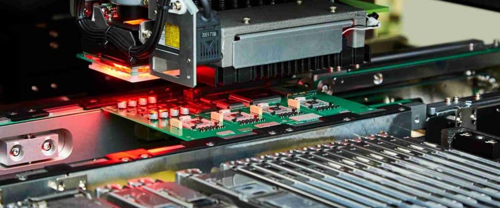
Pick-and-Place Machines
- Robotic machines to pick components from reels or trays and place onto solder paste deposits on the PCB.
- High speed, high precision, and flexible feeder setups.
- Optical and mechanical inspection to verify correct placements.
Reflow Ovens
- Use precisely controlled heat profiles to melt solder paste and form reliable solder joints.
- Multiple heat zones with gradual ramp up and cool down rates.
- Capable of leaded and lead-free solder profiles.
- Configurations include convection, vapor phase, infrared/convection.
Inspection Systems
- Automated optical inspection (AOI) checks component placement, alignment.
- Solder paste, pre-reflow, and post-reflow inspection stages.
- X-ray inspection reveals hidden solder joint issues.
Other Equipment
- Wave soldering – For attaching through-hole components.
- Conformal coating systems – Apply protective coatings.
- Rework/repair stations – Manual component removal/replacement.
- Test and burn-in systems – Validate assemblies.
Advanced Industry 4.0 capabilities like data analytics, machine-machine communication, and automation are increasingly incorporated into SMT lines to improve quality and throughput.
Surface Mount Assembly Process
The surface mount assembly process can be broken down into the following key stages:
1. Solder Paste Printing
- PCB panels are loaded into the printer.
- The solder stencil aligns precisely over the PCB surface.
- Solder paste is dispensed and the stencil squeegee presses paste through apertures onto pads.
- After printing, inspection verifies paste deposits.
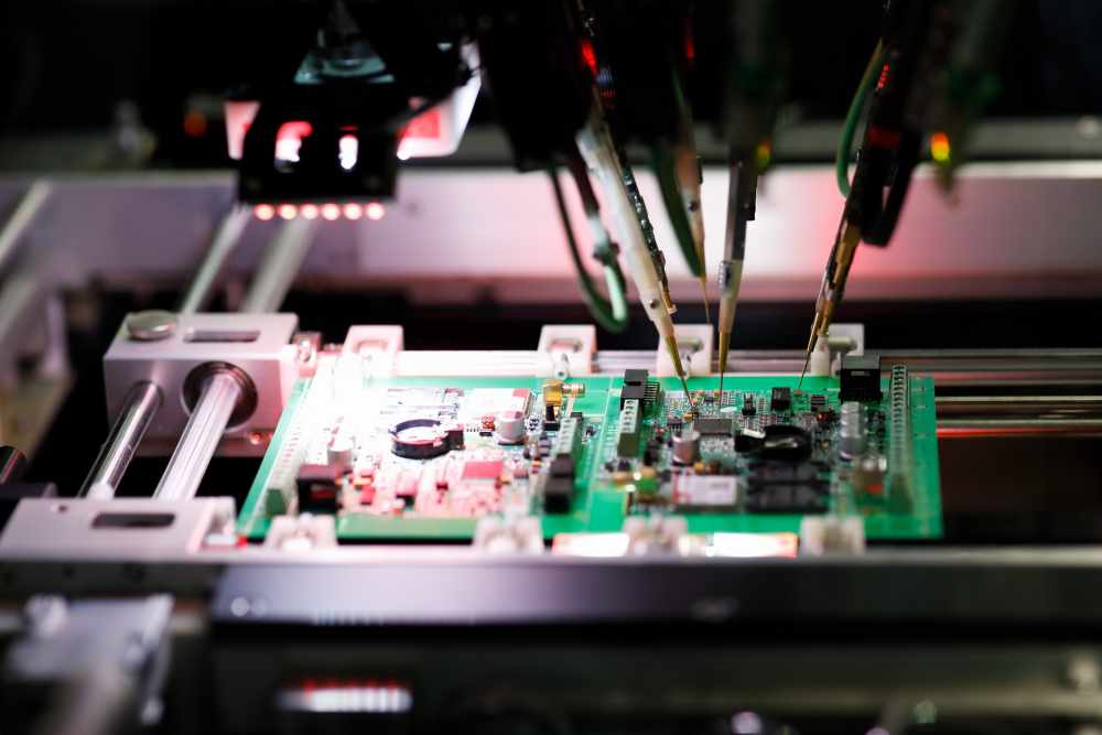
2. Pick-and-Place Component Placement
- PCB panels enter the pick-and-place machine.
- Feeders are loaded with components matching the bill of materials.
- Machine optically aligns to PCB fiducials before placements.
- Vacuum nozzle picks each component and places onto paste.
- Optical inspection checks each placement for accuracy.
3. Reflow Soldering
- Boards with placed components enter the reflow oven.
- Following a controlled thermal profile, boards approach solder melting temperature.
- Solder paste melts, wets to pads/leads, and forms solder joints.
- After peak temperature, boards cool down gradually.
4. Post Soldering Processes
- Visual inspection of solder joints.
- Touch-up and rework of any defective joints.
- Conformal coating application.
- Functional testing of boards.
- Route boards for additional assembly steps.
Repeating this automated sequence across panels of PCBs allows high volume surface mount assembly at optimized cost, quality, and throughput.
Inspection and Testing
Extensive inspection and testing validates quality of the surface mount process:
Solder Paste Inspection
- Verify paste deposits meet tolerances for volume, height, alignment to pads.
- Catch defects before components placed avoiding wasted placements.
Pre-Reflow Inspection
- Optical inspection of all component placements for accuracy.
- X-ray inspection can validate hidden leads correctly placed and aligned.
Post-Reflow Inspection
- Operators visually inspect all solder joints under a microscope.
- Automatic optical inspection (AOI) compares joints to an ideal reference.
- X-ray inspection used for hidden solder joints under BGAs.
Automated Electrical Test (ATE)
- Probes test electrical continuity connections on the board.
- Validates proper functioning of the populated board.
In-Circuit Testing
- Tests analog characteristics, voltages, performance of components loaded on the assembled PCB.
Continuous inspection and testing across the assembly process are crucial for catching defects and ensuring high reliability of completed boards.
Rework and Repair
When inspection finds defects, rework of the affected components is required. This involves:
- Removal of defective component – Using hot air station to melt solder and remove component.
- Site redress – Clean pads and prepare for new component.
- Paste deposit – Dispense fresh solder paste onto pads.
- Component replacement – Pick-and-place new component.
- Localized reflow – Use hot air to form solder joints.
- Inspection – Verify repaired site meets quality standards.
For larger sites with multiple closely spaced components, it may be necessary to remove all components from the affected area before reworking.
Industry Standards
Several key industry standards apply to the surface mount assembly process:
- IPC-A-610 – Acceptability standard for electronics assemblies. Defines quality criteria for SMT assembly and inspection.
- IPC J-STD-001 – Standard for soldering processes including materials, methods, acceptance criteria.
- IPC-7711/7721 – Standard practice for rework, repair and modification of electronic assemblies. Covers proper rework procedures.
- IPC-A-620 – Standard covering requirements for cable, wire and harness acceptance.
- ANSI/ESD S20.20 – Standard for control of static electricity which can damage components.
- ISO 9001 – Quality management system standard covering SMT assembly and quality processes.
Adhering to these industry standards ensures using assembly and inspection practices accepted across the electronics manufacturing industry.
Frequently Asked Questions
Here are some common questions about surface mount assembly processes:
What are the main advantages of SMT over through-hole assembly?
SMT allows higher component density, simplified single-sided assembly, improved reliability, and lower manufacturing costs. Automated assembly is also possible.
What types of components are used in SMT assembly?
SMT includes passive parts like 0402 capacitors and 0603 resistors as well as active ICs in packages like SOIC, QFN, and BGA. Specialized connectors and other components are also used.
What kind of equipment is involved in SMT manufacturing?
Typical SMT equipment includes solder paste printers, pick-and-place machines, reflow ovens, inspection systems, conformal coating applicators, and rework stations.
How are components attached during SMT assembly?
Solder paste is printed on pads. Components are then placed onto the paste deposits. Reflow soldering heats the paste, melting it to form solder joints.
What testing is done to validate SMT assemblies?
Inspection and tests like paste deposit inspection, pre-reflow and post-reflow optical inspection, x-ray inspection, AOI, and electrical testing ensure assembly quality.


