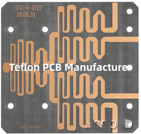
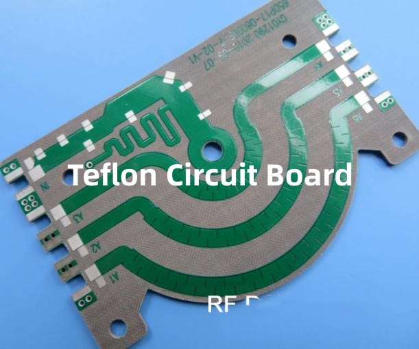
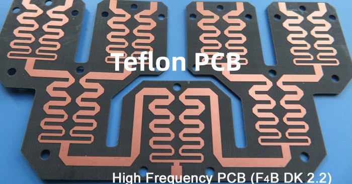
Introduction to Teflon PCB
Teflon PCB (printed circuit board) refers to a type of PCB that uses Teflon as the base insulating material instead of the standard FR-4 material. Teflon, also known as polytetrafluoroethylene (PTFE), is a synthetic fluoropolymer well known for its high heat resistance, chemical inertness, and electrical insulating properties.
Using Teflon as the insulating substrate offers several advantages for PCBs compared to standard FR-4 material:
Higher temperature rating
Teflon has an extremely high melting point of 327°C, allowing Teflon PCBs to withstand much higher temperatures than FR-4 PCBs that have a glass transition temperature of only 130-170°C. This makes Teflon PCBs suitable for high temperature applications.
Better electrical performance
Teflon has lower dielectric constant and loss tangent than FR-4. This results in faster signal propagation, higher frequency capabilities, and lower insertion losses in Teflon PCBs.
Excellent chemical resistance
Teflon offers excellent resistance to a wide range of chemicals like acids, bases, solvents etc. This allows Teflon PCBs to work reliably in harsh chemical environments where FR-4 would be prone to degradation.
Hydrophobicity
The hydrophobic nature of Teflon prevents water absorption, making Teflon PCBs suitable for applications where condensation or water contact is expected. FR-4 absorbs moisture which can lead to leakage currents and dielectric breakdown.
Manufacturing Process of Teflon PCBs

Teflon PCBs follow a similar basic manufacturing process as FR-4 PCBs but with some key differences:
Base Material
The raw material is PTFE resin which is fused into Teflon sheets that form the insulating substrate for the PCB. Filler materials like glass fibers can be added to improve mechanical properties.
Layer Stack-Up
Multiple Teflon substrate sheets are stacked up using epoxy or polyimide adhesive films to build up a multilayer board. The stack-up orientation and sequence are designed as per the required board layout.
Drilling
The adhesive bonded board stack is precision drilled to create holes for mounting components and plated through holes for interlayer connections. As Teflon is difficult to drill compared to FR-4, diamond-tipped drill bits are used.
Metallization
The walls of the drilled holes are plated with copper to form the plated through holes. Entire surface of the board is metallized with copper to form the conductive traces using processes like sputtering, electroplating, or vacuum deposition.
Photolithography
The copper layer is coated with photoresist and then exposed to light through the mask with the required circuit pattern. The unexposed photoresist is developed away, exposing the unwanted copper regions for etching.
Etching
The exposed copper is etched away chemically, leaving only the protected copper circuit pattern on the board. The remaining photoresist is then stripped off.
Solder mask
A solder mask layer is applied to coat the entire board except the solder pads where components need to be joined. This prevents solder bridging between pads during assembly.
Silkscreen
Identifying markings and component legends are printed on the solder mask layer to complete the PCB fabrication.
Testing and Certification
The finished Teflon boards are electrically, mechanically and environmentally tested to verify design compliance before being certified for use in end products.
Applications and Use Cases of Teflon PCBs
Some of the major applications where Teflon PCBs provide technical advantages over standard FR-4 PCBs include:
Aerospace and Aviation
- Airborne radar systems
- Avionics equipment
- Aircraft engine control units
- Missile guidance systems
Teflon PCBs withstand extreme altitude environments and large temperature fluctuations.
Automotive
- Engine control units
- Transmission control modules
- ABS brake systems
- Traction control systems
Teflon PCBs survive under-the-hood high ambient temperatures and vibration.
Medical
- Implantable devices
- Defibrillators
- Diagnostic imaging equipment
Teflon PCBs function reliably inside human body.
Oil and Gas
- Downhole logging tools
- Wellhead instrumentation
- Subsea control hardware
Teflon PCBs operate reliably in harsh subsea conditions.
Military and Defense
- Radars
- Communication equipment
- Avionics systems
- Missile guidance
Teflon PCBs survive extreme shock, vibration and temperatures.
Space Systems
- Satellite electronic systems
- Rocket avionics and telemetry
- Space station instruments
Teflon PCBs handle vacuum environments and thermal extremes during space travel.
In summary, Teflon PCBs provide design engineers with a high reliability PCB substrate option for demanding applications with extreme temperature, chemical, radiation, or other challenging operating environments where standard FR-4 PCBs would not suffice. The superior electrical and physical properties of Teflon make it an ideal PCB material for aerospace, defense, energy and other high-tech applications despite its higher cost.
Comparison Between Teflon and FR-4 PCB Materials

| Parameter | Teflon PCB | FR-4 PCB |
|---|---|---|
| Temperature Resistance | Excellent (327°C) | Moderate (130-170°C) |
| Dielectric Constant | 2.1 | 4.2-4.8 |
| Dissipation Factor | 0.0004 | 0.02 |
| Dielectric Strength (V/mil) | 1000 | 300 |
| Water Absorption | Negligible | 0.2% |
| Chemical Resistance | Excellent | Moderate |
| Volume Resistivity (Ω-cm) | >1018 | >1016 |
| Thermal Conductivity (W/m-K) | 0.25 | 0.29 |
| Coefficient of Thermal Expansion (ppm/°C) | 17 | 14-20 |
| Flexural Strength (MPa) | 55 | >125 |
| Drill wear when machining | High | Low |
| Cost | High | Low |
Frequently Asked Questions
Here are some common queries about Teflon PCBs answered:
Q1. Why is Teflon PCB expensive compared to FR-4?
Teflon base materials are inherently costlier than FR-4 resin. Additionally, Teflon is difficult to drill and requires specialized tooling, adding to fabrication costs. The complex processing required to manufacture Teflon PCBs also makes it pricier than standard FR-4 PCBs.
Q2. Can Teflon PCBs be manufactured using standard FR-4 fabrication processes?
No, the manufacturing processes cannot be the same owing to the vastly different material properties and fabrication challenges of Teflon versus FR-4. Teflon PCB fabrication needs specialized techniques like diamond drilling, plasma etching etc. which are not required for FR-4.
Q3. Does Teflon PCB technology have any limitations?
Teflon PCBs have lower flexural strength than FR-4, making them less suited for flexible PCB applications. The high drill wear also limits the achievable PCB thickness in Teflon. Designs requiring multiple small holes or vias can be problematic with Teflon PCBs.
Q4. Can traces be soldered on Teflon PCBs?
Yes, the copper traces on Teflon PCBs can be hand or reflow soldered. However, good soldering practices should be followed as Teflon does not absorb flux residues, leading to potential corrosion and insulation risk.
Q5. Are special considerations needed while designing Teflon PCBs?
Teflon’s coefficient of thermal expansion being lower than copper should be accounted for in the design to avoid solder joint or plated through hole reliability risks. Spacing vias intelligently to avoid excessive drill wear is also recommended.


