SMA (SubMiniature Version A) connectors are extensively used in high frequency applications up to 26GHz like telecom infrastructure, test equipment, defense electronics, and microwave radio links. Their compact sturdy interface and excellent RF performance makes them a versatile coaxial interconnect option.
But what exactly is an SMA connector in the context of PCBs? And what PCB design considerations ensure achieving optimal performance when utilizing this connector type? Let’s explore those topics in this guide.
We’ll cover SMA connector characteristics, PCB layout guidelines, packaging varieties, recommended components, and compare against similar RF connectors.
SMA Connector Overview

First, a quick refresher on what defines an SMA connector itself, independent of PCBs.
This type of RF connector has four distinguishing attributes:
- Compact Sturdy Design – SMA uses threaded coupling nuts for robust mechanical strength across repeated matings in a small form factor. Stainless steel is common.
- Constant 50 Ω Impedance – The coaxial geometry maintains a controlled 50 ohm impedance to avoid signal reflections during high frequency transmission.
- Flat Pin Termination – A flat tabulous inner pin connection instead of traditionally soldered center pins. This enables solderless PCB mounting.
- Extensive RF Compatibility – Broadband performance exceeding 26GHz with low VSWR across microwave and mmWave spectrums.
Now let’s explore PCB integration specifics…
SMA Connectors for PCBs
Several packaging varieties tailor SMA connectors for integration onto printed circuit boards. These include Through Hole, Edge Mount, and Surface Mount configurations.
Here is a brief overview before we dive deeper into PCB layout considerations:
Through Hole
This traditional variety uses plated through holes for securing to boards. The connector protrudes out from the top side while bottom side solder joints anchor it firmly.
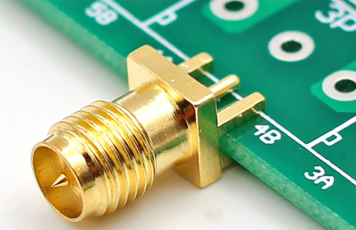
Edge Mount
Alternatively, edge mount SMA connects position along the PCB periphery secured with bottom side soldering alone. No through holes are needed.
Surface Mount
For low-clearance applications, surface mount SMA adapters solder directly to pads on the top PCB layer. Their compact footprint consumes minimal area.
Now let’s move on to some of the most vital PCB layout considerations when working with SMA connectors for high frequency circuits…
PCB Layout Guidelines
Careful board layout is critical to achieve optimal performance from SMA connectors carrying microwave signals. Several principles related to impedance control, resonances, and manufacturability should guide designs.
1. Tune Trace Widths
The first priority is tuning the signal trace width from the SMA pin to the desired characteristic impedance. This is typically 50 ohms.
Use an online calculator to determine the appropriate trace width and clearance for your PCB stackup. Wider traces lower impedance while narrower ones increase it.
2. Minimize Stub Length
Any protruding transmission line segment reflecting signals back towards the source constitutes an unwanted stub.
Excess pin length inside SMA connectors can create problematic stubs. Clip pins to eliminate extra length beyond what’s required for soldering or assembled components.
3. Include Ground Stitching
Frequent vias connecting the ground planes along the signal path helps isolate noise while maintaining return current continuity. These avoid ground displacement currents that can couple or radiate noise.
4. Solid Ground Plane
Use a continuous, solid copper fill underneath the SMA connector in all ground layers. Avoid any voids or pouring irregularities which hinder ideal RF performance.
5. Careful Component Placement
Strategically place termination components like resistors or capacitors close to the SMA junction with very short traces to minimize added loop inductance.
6. Continued Impedance Matching Throughout
Any transmission line impedance deviations beyond the SMA interface degrade signals via reflections. Continue matching 50 ohm geometries for all trace routing connected to the port.
By applying concepts like the above during layout, engineers mitigate numerous risks to signal integrity across PCBs supporting SMA connections.
Recommended SMA Components

Besides layout factors, component selection also impacts results achieved from SMA interfaces. Let’s overview some component recommendations when specifying boards with SMA ports.
PCB Stackup
SMA connectivity favors PCB dielectrics with tightly controlled thickness/tolerance such as:
- Polyimide
- PTFE (Teflon)
- FR408HR
- Megtron 6
Thinner dielectrics are generally preferable for easier impedance tuning.
Plating
Immersion silver plating with nickel underlayer offers the best solderability and minimal insertion loss at microwave frequencies.
Avoid HASL or ENIG platings. These have inferior conductivity and connection reliability that degrade signal performance.
SMA Connectors
Prioritize SMA connector variants with flanged board locks, adequate PCB hole annular rings, extended solder tabs, and precision threadings. These provide superior mechanical anchoring and RF performance.
favour brands like Rosenberger, Amphenol, Radiall, Omnetics and Southwest Microwave when sourcing SMA connectors.
Comparing SMA with Similar Connectors
Now that we’ve covered SMA connectors in depth, it is useful to contrast against some alternate RF connector solutions serving analogous purposes.
Below we’ll compare technical specs between SMA, SSMA, SMP, and MCX connectors often used in microwave circuits and modules.
SMA vs SSMA
SSMA (Subminiature Snap-On Version A) shares the same inherent coaxial design as SMA with a screw-coupled locking mechanism.
However, SSMA uses snap-on MIL-PRF 39012 bayonet coupling for quicker connections rather than threaded nuts. This sacrifices some ruggedness and pulls apart under lower force thresholds.
SMA vs SMP
SMP (SubMiniature Push-on connector) also shares the 50 ohm SMA transmission line architecture but with push-pull friction locking rather than threaded couplers.
This achieves moderate ruggedness and weather protection without rotation. It allows high density arrangements, but with lower vibration tolerance than SMA.
SMA vs MCX
MCX (MicroCoaX) is smaller, lighter, and cheaper than SMA. But MCX is limited lower frequencies up to 6GHz and carries lower power thresholds.
MCX utilizes snap-on friction couplers without threading or bayonets resulting in weaker locking strength.
Where size or weight overrides ruggedness needs, MCX displaced SMA in some mobile and IoT devices.
SMA Connectors Compared
| Parameter | SMA | SSMA | SMP | MCX |
|---|---|---|---|---|
| Frequency (max) | 26.5 GHz | 26.5 GHz | 65 GHz | 6 GHz |
| Power (max) | Up to 10W | Up to 2W | Up to 2W | 0.3W |
| Coupling mechanism | Threaded | Bayonet snap-on | Friction push-pull | Friction snap |
| Environmental sealing | Good | Good | Fair | Fair |
| Locking strength | Excellent | Moderate | Moderate | Fair |
| Cost | Medium | Medium | High | Low |
As highlighted in the comparison, SMA distinguished by excellent frequency range, rugged locking, and moderate cost at the expense of compactness. This suits them well to replaceable test equipment modules, instrument interfaces, and medium power antenna links.
Their wide adoption across industries stems directly from these balanced electrical and mechanical capabilities.
Conclusion

In summary, we’ve explored SMA connectors in the context of PCB integration covering:
- Key characteristics like impedance control, pin interfaces, and RF performance
- PCB layout principles to follow including stubs, stitching, and components placement
- Recommended materials and platings
- How SMA contrasts with alternate connectors like SSMA, SMP, and MCX
By applying the guidelines covered here when integrating SMA ports onto printed circuit boards, engineers can achieve repeatable connectivity and signal integrity across a wide array of microwave applications and products.
Careful validation using S-parameters and TDR measurements remains vital as well to verify final RF performance prior to release.
SMA Connector FAQs
Some frequently asked questions around utilizing SMA connectors on PCBs:
Are SMA connectors suitable for digital signals or purely analog RF?
While designed expressly for microwave signals, SMAs can additionally carry fast digital signal edges or pulse trains up to roughly 6+ Gbps effectively. Their controlled impedance environment reduces Digital Signal Integrity (DSI) risks.
What are some examples of PCBs and products using SMA connectors?
Test equipment like vector network analyzers, antenna/radar systems, avionics modules, satcom hardware, and various RF instrumentation interfaces rely on SMA connectivity.
Why are tighter PCB hole tolerances needed for RF connectors?
Unlike power connectors, even small alignment deviations between board holes and mating RF connectors can introduce signal reflections or impedance discontinuities. Keep tolerances under 0.10mm.
What materials should avoid using near SMA connectors on a PCB layout?
Avoid ferrite materials, heavily conductive metals, or other microwave-interactive substances adjacent to SMA connectors which can potentially couple interference.
How should I test assembled PCBs with SMA ports?
Leverage VNA or TDR testing to validate impedance matching, characterize insertion loss by frequency, and identify any interface or soldering issues before further integration.


