
Printed circuit boards (PCBs) are ubiquitous in all modern electronics serving as the foundational component for mounting and interconnecting electronic components. They provide the mechanical structure and electrical connectivity backbone in most electronic devices and equipment.
There is a diverse variety of PCB types designed to serve different applications across consumer electronics, computing, telecommunications, industrial equipment, automotive, aerospace, and other sectors. These circuit boards differ in their materials, conductive layer structure, manufacturing processes and performance capabilities.
This article provides an overview of the major categories and varieties of PCBs available in the market. We will examine the attributes of each type along with their typical applications.
Types of Circuit Boards

PCBs can be classified based on:
- Number of conductive layers
- Base insulation material composition
- Rigidity vs. flexibility
- Manufacturing process scale
The main categories along with some common varieties are summarized below:
By Number of Conductive Layers
1. Single Sided
- A single copper layer on one side of the insulating substrate.
- Low component density and limited interconnects.
- Used in simple, low cost electronics.
2. Double Sided
- Copper layers on both sides of the substrate.
- Allows increased component density and more interconnections.
- Most common board for modest complexity needs.
3. Multilayer
- 3 or more conductive layers interleaved using insulating dielectric.
- Allows very high component density and interconnects.
- Used for complex, compact electronics.
By Base Material Composition
1. FR-4 Boards
- Composite material of woven fiberglass and flame resistant epoxy resin.
- Most common low-cost PCB material.
- Suitable for modest frequencies and performance.
2. High Frequency Boards
- Use special substrates like PTFE, ceramic, polyimide.
- Essential for microwave, RF and other high frequency apps.
- Offer tightly controlled electrical characteristics.
3. Flexible Boards
- Use flexible polymer substrates like polyimide.
- Can be flexed, twisted, bent during use.
- Suited for dynamic flexing environments.
By Manufacturing Scale
1. Prototype Boards
- Small quantity PCBs for design testing and evaluation.
- Fast turnaround times with minimal tooling.
- Allow circuit validation before high volume mfg.
2. Production Boards
- Manufactured in large volumes once design is finalized.
- Require process and test optimization.
- Tight tolerances and process controls.
We will now examine each PCB variety in more detail along with their attributes and applications.
Types of PCBs by Conductive Layer Structure
Single Sided Boards
These have a single layer of copper traces on one side of the insulating substrate. Key properties include:
- Simplest and most basic PCB structure.
- Typically low component densities.
- Limited interconnectivity since traces routes are restricted to one layer.
- Low fabrication costs due to faster processes and higher yields.
- Often used in cost-sensitive products.
Typical applications include basic consumer electronics, appliances, toys, desktop peripherals, and other non-complex circuits with minimal component requirements.
Double Sided Boards
These have conductive copper layers on both sides of the substrate. Salient features are:
- Provides increased board area for more component placement and routing.
- Allows greater trace interconnectivity between components via vias.
- Supports higher PCB complexity for a modest cost increase over single sided.
- Most common general purpose PCB type for moderate complexity needs.
- Extensively used across consumer, industrial, medical and automotive products.
Typical applications include home appliances, power tools, office equipment, network routers, sensors, motor controllers etc.
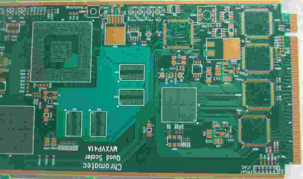
Multilayer Boards
These contain four or more conductive layers interleaved between insulating dielectric substrates. Key attributes are:
- Multiple conductive layers allow very high component densities.
- Large number of layers provides tremendous routing capacity.
- Blind and buried vias facilitate interconnections between inner layers.
- Allows construction of complex, compact and efficient circuitry.
- Used where size constraints require small form factor.
- Substrate materials determine frequency response.
Applications utilizing multilayer boards include smartphones, tablets, computers, servers, telecom infrastructure, avionics, industrial controls, and medical electronics.
PCB Types by Base Material Composition

FR-4 Boards
The substrate uses a woven fiberglass reinforcement impregnated with an epoxy resin. Features include:
- Most common low-cost PCB material.
- Provides reasonable thermal performance.
- Electrical properties suitable for kHz to lower MHz frequencies.
- Widely used for general purpose consumer and industrial electronics.
- Extensive process familiarity due to widespread usage.
- Available as single, double sided and multilayer boards.
Typical applications are home appliances, power tools, automotive circuits, test equipment, industrial controls, and consumer electronics.
High Frequency Boards
These utilize advanced dielectric substrates tailored for high frequency response. Types include:
PTFE (Teflon) Boards
- Low dielectric loss even at microwave frequencies.
- Excellent electrical stability under wide temps.
- Used for radar, telecom, satellite and defense RF circuits.
Ceramic Filled PTFE Boards
- Provide dimensional stability lacking in pure PTFE.
- Enable tighter tolerances for better manufacturability.
- Used for high volume wireless and cellular products.
BT (Bismaleimide Triazine) Boards
- Offer low moisture absorption and high Tg.
- Used in multilayer boards for radar and communication.
Polyimide Boards
- Withstand very high temperatures up to 300°C.
- Used for down-hole, aerospace and other extreme environs.
Rogers Boards
- Provide precisely controlled dielectric properties.
- Ideal for stripline and microstrip high frequency uses.
High frequency boards support specialized RF, microwave and other demanding applications requiring tightly controlled electrical characteristics and stable high frequency response.
Flexible Boards
These use flexible polymer substrates that allow dynamic bending and flexing:
Polyimide Boards
- Most common flexible board material.
- Provide reasonable bend radius and good high temp rating.
- Used for small foldable consumer electronics.
Polyester Boards
- More economical option to polyimide.
- Provide adequate flexibility for limited bending.
PVC Boards
- Lowest cost flexible substrate option.
- Used for simple interconnect flex circuits.
Flexible boards are essential in applications where static rigid boards cannot accommodate continuous flexing, repeated bending and tight radius folds that occur in use. Examples include foldable displays, wearable devices, robotic joints and harnesses.
PCB Types Based on Manufacturing Scale
Prototype Boards
These are manufactured in low volumes for initial proof-of-concept, evaluation and testing:
- Small batch orders from just a few up to ~50 boards.
- Minimal tooling and tight process controls.
- Fast turnaround times within a few days.
- Allow verification of circuit design before high volume mfg.
- Critical for rapid prototyping during product development.
Applications include R&D, product design iterations, pilot deployments, technology evaluation, and pre-production testing.
Production Boards
These are manufactured in large series once the product development is complete:
- Batch orders from hundreds to millions of boards.
- Require process optimization for efficiency and yields.
- Tight tolerances, process controls and testing needed.
- Prioritize repeatability, reliability and cost over timelines.
- Used once design is finalized for commercial production.
Applications are delivery of boards to electronic OEMs for end products spanning consumer, industrial, automotive, medical and other industry verticals.
This covers the most common PCB types segmented by conductive layer count, base material composition and manufacturing volumes along with their typical applications.
Comparative Analysis of Key PCB Varieties
| Parameter | Single Sided | Double Sided | Multilayer | FR-4 | High Freq. | Flexible | Prototype | Production |
|---|---|---|---|---|---|---|---|---|
| Layer Count | 1 | 2 | 4+ | 1-8+ | 2-20+ | 1-8 | 1-12 | 2-32+ |
| Lead Count | Low | Moderate | High | Low-High | High | Low-Moderate | Low-Moderate | Moderate-High |
| Complexity | Low | Moderate | High | Low-High | Moderate-High | Low-Moderate | Low-Moderate | Moderate-High |
| Frequency | Low-Moderate | Low-Moderate | Low-High | Low-Moderate | High | Low-Moderate | Low-Moderate | Low-High |
| Flexibility | Rigid | Rigid | Rigid | Rigid | Rigid | Flexible | Rigid/Flex | Rigid |
| Cost | Low | Moderate | High | Low | High | Moderate | Low-Moderate | Low-High |
| Volume | Low-Medium | Medium-High | Medium-High | Low-High | Low-Medium | Low-Medium | Low | High |
| Lead Time | Fast | Medium | Slow | Medium | Slow | Slow | Fast | Slow |
This summarizes and compares key parameters across the major PCB varieties encompassing layer count, complexity, frequency response, flexibility, relative cost, typical volumes manufactured and production lead times.
Conclusion

There is a wide gamut of PCB types tailored to meet the varied design complexity, performance, mechanical, environmental and cost requirements across diverse electronics applications:
- Layer count defines board complexity – single sided offers basic interconnects while multilayer supports very advanced circuitry.
- Board materials like FR-4, ceramics and polyimides provide the required combination of electrical, thermal, mechanical and environmental performance.
- Flexible boards enable applications involving continuous bending and flexing during use through polymer substrates.
- Prototype boards facilitate development and testing while production boards are optimized for commercial manufacturing.
In summary, PCB characteristics span a tremendous range – from simple single sided boards using FR-4 substrates to complex multilayer circuits employing advanced RF materials; from small batch prototypes to mass produced boards; and from the stiffest ceramics to highly flexible polymers. This diversity of PCB types equips designers to select the optimal solution tailored to their specific application requirements.
Frequently Asked Questions
Question 1: What are some key considerations when selecting a PCB type for an application?
Some major factors are:
- Number of components and required interconnect complexity
- Electrical performance needs – frequency range, losses, noise, etc.
- Environmental conditions – temperature range, vibration, etc.
- Mechanical requirements – size, shape, rigidity, etc.
- Cost targets – can dictate allowable materials and layer counts
- Production quantities – low volume prototype vs mass production
- Testing and qualification requirements
Question 2: What are the main differences between FR-4 and high frequency PCB substrates?
FR-4 provides respectable performance at modest cost but has higher losses, poorer electrical consistency and weaker high frequency characteristics compared to advanced microwave and RF substrates. High frequency boards offer tightly controlled dielectric properties for precise impedance control, low losses and stable response across temperature at an increased cost.
Question 3: What are some key considerations when selecting flexible PCB materials?
Important parameters are minimum bend radius, flex life, dynamic bending stresses, temperature rating, chemical resistance, thickness requirements and impedance control needs. Materials like polyimide and polyester provide a good balance of electrical and mechanical flex performance.
Question 4: How do PCB prototype boards differ from production boards?
Prototype PCBs emphasize fast turnaround on small batches for design validation during development. Production PCBs focus on high yields, repeatability and reliability for large volume manufacturing. They involve more extensive DFM optimizations, tighter tolerances and process controls.
Question 5: When would a single sided PCB be unsuitable for an application?
For circuits requiring more than a minimal component count or interconnect complexity, single sided boards become highly constrained in routing capability leading to undesirable workarounds. The lack of a bottom conductive layer also limits ground plane effectiveness. In such cases, at least a double sided board would be preferable.


