
Introduction
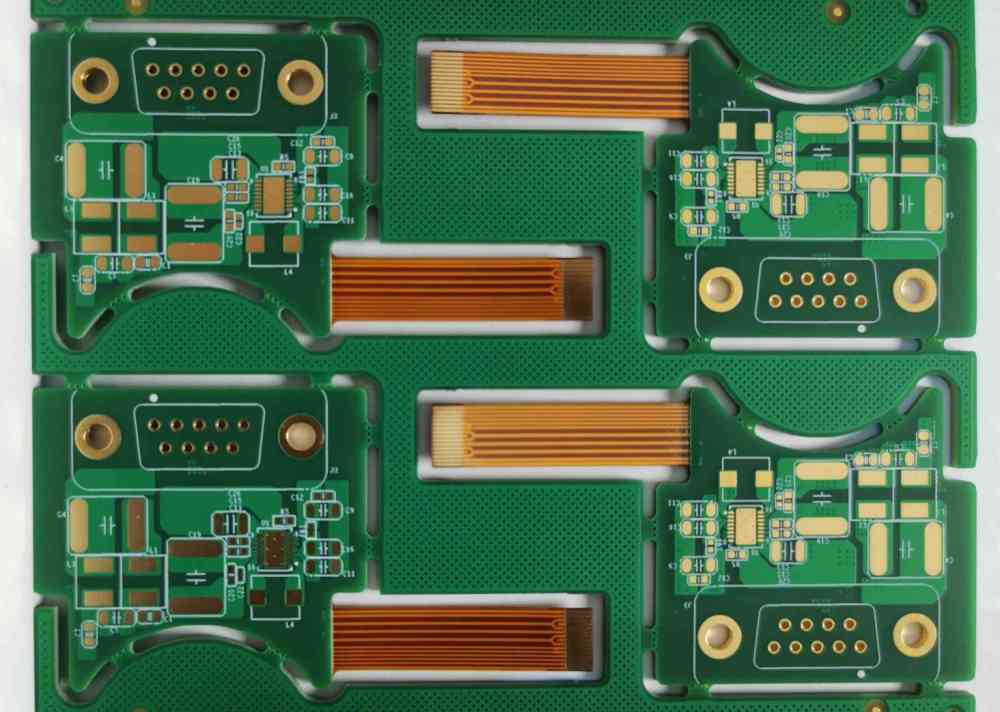
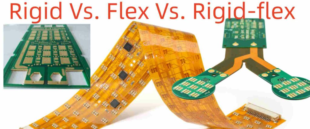
Printed circuit boards are available in three main structures – rigid, flexible, and flex-rigid combinations. Each has their own fabrication methods, assembly considerations, and cost structure based on the unique materials and technologies involved.
This article provides a detailed comparison between flexible PCBs, traditional rigid boards, and hybrid rigid-flex boards in terms of their manufacturing processes, assembly procedures, quality control needs, and cost trade-offs.
Analyzing these key differences helps in selecting the optimal board type for an application based on technical requirements, design constraints, and budgetary factors.
PCB Manufacturing Comparison
PCB fabrication transforms design files into physical boards by building up conductive copper layers and insulating dielectric layers. Here is a comparison of manufacturing steps for the three board types:
Board Materials
| Rigid PCBs | Flex PCBs | Flex-Rigid PCBs | |
|---|---|---|---|
| Substrate | FR-4 glass epoxy. Other options like PTFE, ceramic, polyimide. | Polyimide (Kapton), polyester (PET), polyethylene | Combination of rigid and flexible substrates. |
| Copper Foil | 1oz (35μm) common. Half oz. to 3 oz. available. | 1⁄2 oz (17μm) typical. 1oz max. | Varies – thick copper on rigid portions, thin copper for flexible areas. |
| Dielectric Layers | Prepreg bonding sheets. FR-4 glass epoxy core. | Adhesive bonding films. Polyimide commonly used. | Combines rigid prepregs and flexible bonding films. |
- Rigid PCBs use rigid FR4 material while flex PCBs use thin flexible films. Flex-rigids combine both types of substrates.
- Thick copper sheets are etched to form conductors for rigids while thin copper foils are used on flex PCBs.
- Prepregs bond layers on rigids. Flex-rigids can use both prepregs and flexible adhesives.
Layer Fabrication
| Rigid PCBs | Flex PCBs | Flex-Rigid PCBs | |
|---|---|---|---|
| Lamination | Stackup heated and pressed for curing prepregs. | Layers bonded by heat and adhesive activation. | Combination of lamination and adhesive bonding. |
| Alignment | Precision alignment of layers is critical. | Even more critical due to thinner materials. | Toughest alignment to assemble dissimilar layer stackup. |
| Etching | Strong etchants like cupric chloride used. | Milder etching to avoid over-etching thin copper. | Can use different etchants in rigid and flex areas. |
| Hole drilling | Mechanical drilling. Excellent dimensional accuracy. | Punching may be used. Drilling requires backup support. | Stackup thickness varies – needs adjustment of drilling parameters. |
| Via Plating | Electrolytic plating builds up copper thickness . | Thin copper limits plating thickness. | Plating process tailored separately for rigid and flex vias. |
| Patterning | Photolithography and etching creates fine features. | High resolution imaging is crucial for dense flex circuits. | Panelization considers rigid board outlines. |
- Rigid boards can withstand high temperature and pressure lamination while flex layers are bonded together with adhesive films.
- Precise alignment is critical for multilayer stackup, especially complex flex-rigid configurations.
- Thinner copper and flexible materials need special handling during fabrication processes like etching, drilling and plating.
Finishing
| Rigid PCBs | Flex PCBs | Flex-Rigid PCBs | |
|---|---|---|---|
| Solder mask | Liquid photoimageable (LPI) mask most common. | Polyimide coverlay, LPI or inkjet solder masks. | Polyimide in flex areas, LPI on rigid sections. |
| Legend printing | Inkjet or UV ink printed legends. | Polyimide allows laser ablated markings. | Combination of methods suited to different zones. |
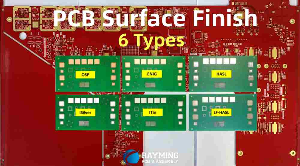
| Surface finish | OSP, immersion tin, ENIG, hard gold popular. | Entek or electroless nickel barrier preferred for flex reliability. | Selective finishing in rigid and flex areas. |
| Singulation | Individual boards routed apart. | Die cutting flex boards while retaining stabilizing frames or tabs. | Complex multi-step routing, scoring and breakaway tab designs. |
- Solder mask, legend printing and surface finishes tailored for flexible substrates.
- Singulation process adapted for flex materials while retaining mechanical stability.
- Flex-rigid boards require localized finishing processes.
PCB Assembly Comparison
Populating boards with components requires optimizing assembly processes for each technology:
Board Handling
| Rigid PCBs | Flex PCBs | Flex-Rigid PCBs | |
|---|---|---|---|
| Fixtures/carriers | Simple rigid frames suffice. | Dedicated fixtures stretch and stabilize thin flex boards during assembly. | Specialized frames maintain rigid-flex shape. |
| ESD handling | Use of wrist straps, heel straps and grounded equipment. | ESD protection required for static sensitive flex boards. | ESD protocols followed for entire assembly area. |
| Board support | Rigid board retains shape. | Tooling, vacuum hold-down or adhesives used to support flex shape. | Supports maintain rigid-flex stability. |
- Flexible boards need specialized fixtures for handling and avoiding damage. Flex-rigids also require custom framing solutions.
Soldering Processes
| Rigid PCBs | Flex PCBs | Flex-Rigid PCBs | |
|---|---|---|---|
| Soldering methods | Reflow soldering mostly used. Some wave soldering. | Mainly reflow soldering. Selective wave soldering. | Reflow preferred. Wave soldering on limited basis. |
| High temperature exposure | Withstands multiple passes through reflow. | Polyimides have lower maximum temperature – single reflow pass. | Rigid sections can allow multiple reflow passes. |
| Process control | Standard reflow oven thermal profiling. | Tighter profiling needed for heat sensitive materials. Thermocouples used. | Independent profiling based on location – rigid or flex area. |
| Component stresses | Minimal CTE mismatch issues. | Polyimide and flex PCB expansion differs from components. | Manage stresses at component interfaces between rigid and flex sections. |
- Reflow thermal profiles must be precisely controlled for heat sensitive flexible boards.
- Component attachment processes have to manage thermal expansion mismatch stresses.
Component Types
| Rigid PCBs | Flex PCBs | Flex-Rigid PCBs | |
|---|---|---|---|
| Component packages | All standard component packages usable. | ICs with flexible leads preferred. Avoid bulky or tall parts. | Component selection optimized separately for rigid and flex zones. |
| Connectors | High density connectors easily mounted. | Lower contact density flex connectors used. | Area dependent connector selection. |
| Adhesives | Minimal use of adhesives or potting. | Epoxy or silicone adhesives used for strain relief. | Adhesive application focused on high strain areas. |
- Lightweight flexible component packages suit flex board assembly.
- Connectors and adhesives chosen based on rigid or flexible sections of the PCB.
Quality Control
| Rigid PCBs | Flex PCBs | Flex-Rigid PCBs | |
|---|---|---|---|
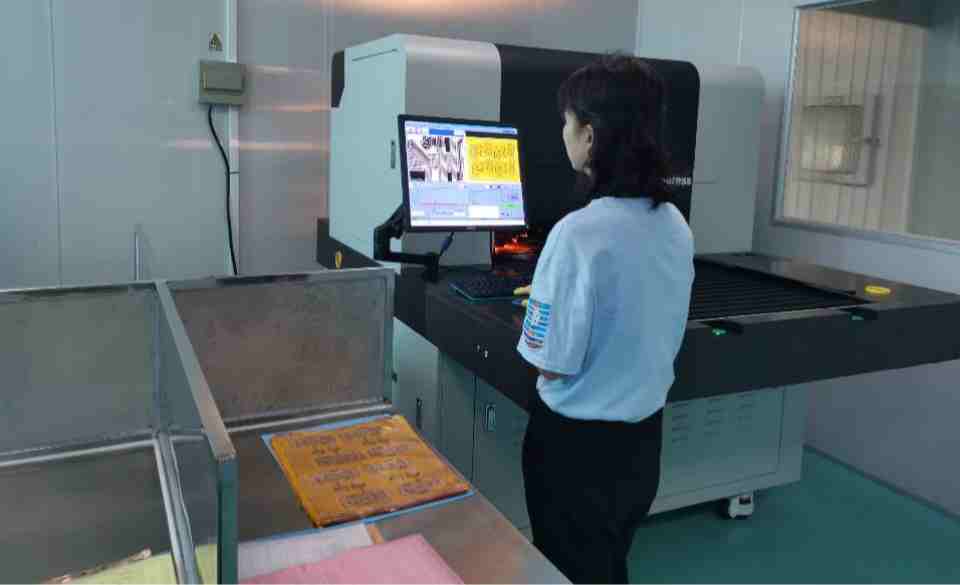
| Inspection focus | Solder joint quality and component placement. | Damage like cuts or tears on thin flex substrates. | Combination of rigid and flex defect modes. |
| Testability | Test pins access through entire rigid board. | Flying probe testing preferred for flex boards. | Both flying probe and fixture-based testing used. |
| Reliability tests | Focus on thermal cycles, vibration, and drops. | Dynamic bend stress tests essential for flex boards. | Assess both mechanical robustness and flexibility. |
- Flex circuits require specialized inspections focused on material damage.
- Specific environmental tests validate mechanical performance.
- Rigid-flex testing combines electrical, interconnection, and dynamic bending reliability.
Cost Comparison
PCB cost depends on both manufacturing and assembly factors:
Manufacturing Cost Drivers
| Rigid PCBs | Flex PCBs | Flex-Rigid PCBs | |
|---|---|---|---|
| Materials | Standard FR4 prepreg and copper foils. | Polyimides, adhesives and thin copper premium priced. | Combination raises materials cost. |
| Layer count | Multilayer rigids add minimal cost. | Each flex layer adds more cost due to precision alignment. | High layer counts very expensive. |
| Fabrication processes | Mature processing with economies of scale. | Special flex processes require dedicated tools and expertise. | Complex methods require investment. |
| Yield | Established process yields. | Thin flex materials affect yields. | Rigid and flex process yields compound. |
| Panel utilization | High material utilization with rectangular PCBs. | Flex substrate use efficiency lower. | Hybrid layouts increase material waste. |
| Tolerances | Standard PCB tolerances suffice. | Tight tolerances needed for flex alignment and bends. | Precise tolerances required adds cost. |
| Testing | Low Touch labor for in-circuit test. | Additional functional and bending tests. | Combined electrical, mechanical, environmental testing. |
- Special materials, layer fabrication, lower yields and touch labor involved in flex PCB manufacturing increase costs.
- Design complexity and integration challenges further raise cost of flex-rigid boards.
Assembly Cost Drivers
| Rigid PCBs | Flex PCBs | Flex-Rigid PCBs | |
|---|---|---|---|
| Board handling | Minimal manual handling steps and fixtures. | Dedicated tooling for flex control adds labor. | Complex handling fixtures and operations. |
| Soldering | High volume soldering processes. | Lower volume specialty flex soldering. | Combination of multiple techniques. |
| Component types | Wide range of component selections. | Limited tested flex component ecosystem. | Need to match components to board zones. |
| Connectors | Standard connectors used. | Specialized lower-density flex connectors. | More connectors required. |
| Conformal coating | Usually not required. | Coating for flex reinforcement adds cost. | Multi-step selective dispensing process. |
| Inspection | Standard quality assurance protocols. | Rigorous inspection for damage. | Inspection time and complexity increase. |
| Testing | Low cost structural testability. | Difficult fixture or flying probe testing. | Expensive combination testing. |
- Additional constrained handling, inspection, and test procedures for flex assembly increase cost.
- Component selections need to be compatible with flex and rigid areas in flex-rigid designs.
Cost Model Comparison
A summary of the typical pricing models highlights the cost differences:
| Rigid PCBs | Flex PCBs | Flex-Rigid PCBs | |
|---|---|---|---|
| Major cost factors | Board area, layer count | Layer count, dielectric type, minimum bend radius | Layer count, hybrid materials, tolerance |
| Pricing model | Based on area, layers | Based on dielectric type and layers. Minimum charges apply. | Based on overall layer count. Surcharges for vias spanning rigid-flex interface. |
| Volume discounts | High volume leads to discounts | Moderate volume discounts | Low volume, high mix – limited discounts |
| NRE/Tooling costs | Minimal non-recurring engineering costs | Significant NRE for fabricating flex layers | Very high NRE due to complexity |
| Assembly cost | Low cost per component or area | Higher cost for specialized processes | Max cost due to manual steps |
- Rigid boards offer basic pricing scaled to volume. Flex and flex-rigid pricing is complex with larger fixed costs.
- Flex-rigid combines the highest expenses of both flex fabrication and assembly.
Conclusion
- Rigid, flex, and flex-rigid PCB technologies each have unique manufacturing and assembly processes tuned for their specific material properties.
- Flexible PCBs provide advanced capabilities like dynamic flexing and 3D configurations but at higher fabrication cost.
- Flex-rigid boards allow zoning of rigid and flex sections but require complex and expensive hybrid processes.
- Assembly procedures must also be tailored to accommodate the specialized handling and soldering needs.
- Understanding these technology-driven cost differences helps in selecting the optimal board construction for an application based on performance requirements, design factors and budgetary constraints.
PCB Technology Selection FAQs
Q: When is rigid PCB technology best suited in an application?
A: Rigid boards provide the most cost-effective solution for high volume, less complex PCBs requiring minimal flexibility. Applications with high layer counts or dense interconnects also favor rigid boards.
Q: What are some indicators that a flex PCB should be considered?
A: The need for dynamic flexing, simple layer construction under 6 layers, tight space constraints requiring folding/wrapping, 3D form factors and repeated bending cycles favor choosing flex PCB technology.
Q: How to determine if a rigid-flex design adds value vs. a pure rigid or flex approach?
A: Rigid-flex should be considered when discrete rigid and flex zones are clearly defined, component types differ between sections, and interconnect needs justify the added cost. It avoids compromising on rigid board or flex PCB limitations.
Q: What are important design considerations while designing a flex PCB?
A: Account for required bend radius, plan layout so conductors cross folds along their lengths, use tear-stop features at edges, implement stiffeners and covers for protection, accommodate thermal expansion differences, and follow fabrication tolerances.
Q: How does rework and repair compare between rigid and flex PCBs?
A: Rigid PCBs allow simpler component removal and replacement. Flexible boards require more care during rework to avoid damage with limited replacements possible. Failed rigid boards can be more easily scrapped and replaced.


