Wire to board connectors create removable electrical interfaces between wires or cables and printed circuit boards (PCBs). They allow signals and power to be transferred from an external system onto a PCB through a pluggable connection.
Wire to board connectors come in a vast array of styles, pitches, pin counts, termination methods and materials to accommodate various applications and PCB design needs. Selecting suitable wire to board connectors requires understanding key properties like current rating, density, durability, termination style, and cost.
This article provides a comprehensive overview of wire to board connector types, design considerations, installation, reliability factors and usage in electronics. Read on for an in-depth look at implementing removable interconnects from wires to boards using wire to board connectors.
Wire to Board Connector Overview
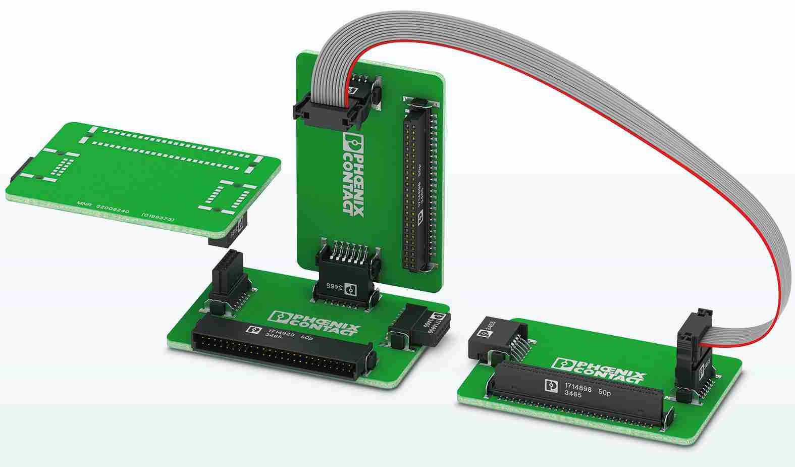
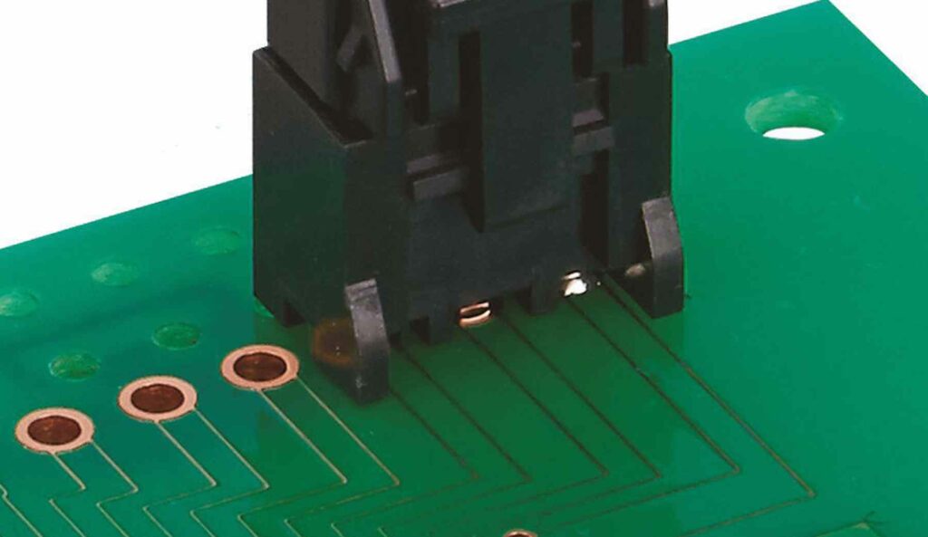
Wire to board connectors provide an array of contact pins or blades soldered to a PCB that mate with a plug containing socket contacts wired to an external cable or harness. The main components include:
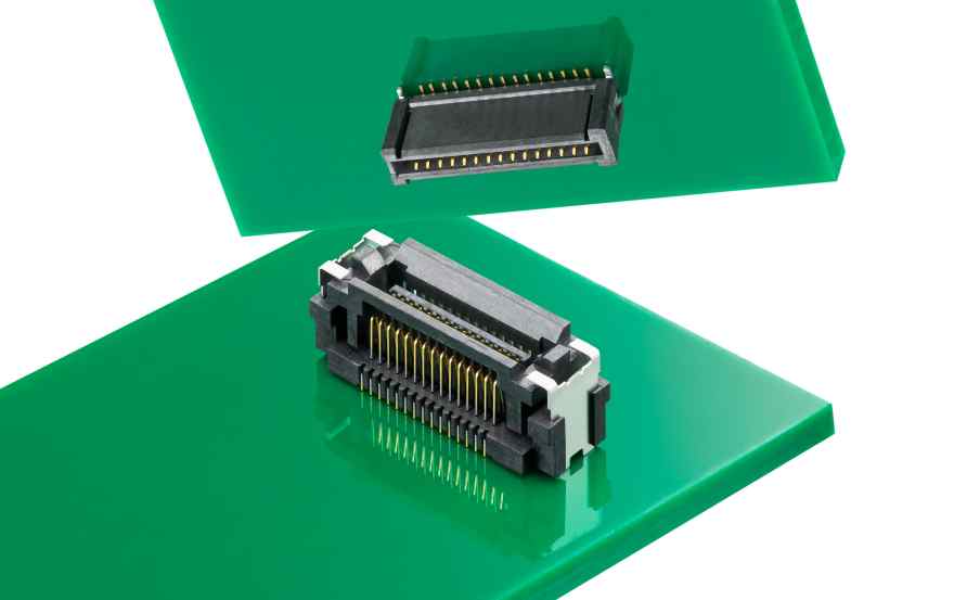
Plug Housing – Molded plastic or metal shell containing socket contacts that engage with the pins on the PCB. May include strain relief for cable anchoring.
Pin Header – Header mounted on PCB with pins that mate with plug sockets. Available in through-hole or surface mount termination.
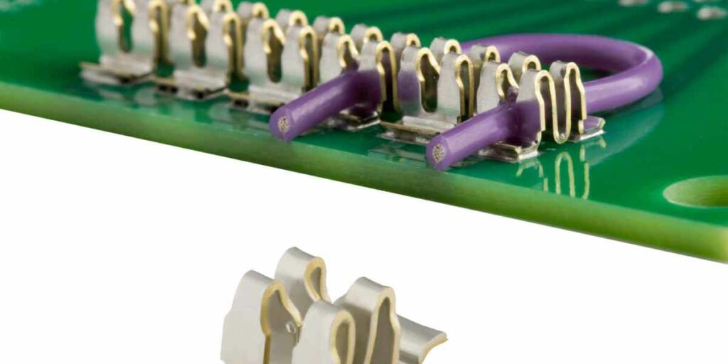
Contacts – Spring metal pins and sockets make the electrical connection when mated. Various material and plating options.
Locking Features – Latches, screws, clips or other mechanical means to secure mating.
When connected, the wire to board connector creates a removable electrical bridge between the cable and PCB. Different arrangements accommodate varied needs.
Reasons to Use Wire to Board Connectors
Wire to board connectors offer several advantages versus permanent soldered wire connections:
- Removability – Connectors allow wires to be detached from a PCB for servicing, storage or transport.
- Interchangeability – Standard connectors enable swapping peripheral devices or cables quickly.
- Signal Breakout – Break wire signals out onto a PCB with proper connectors.
- Field Wiring – Assemble external harnesses separately and connect on-site with connectors.
- Durability – Robust connectors withstand repeated matings better than direct soldering.
- Orientation – Polarized connectors prevent improper insertion.
- Strain Relief – Integrated cable grips reduce stress on connections.
- EMI Containment – Metal shells shield signals for improved emissions and immunity.
Wire to board connectors facilitate quick assembly and reconfiguration of electronics systems.
Wire to Board Connector Types
Many types of wire to board connectors exist to address varied applications. Common classifications include:
Pin Header Connectors
- Male pins solder onto PCB
- Female socket plug for wires
- Found in single row, dual row and 2D grid arrays
Card Edge Connectors
- Contacts along edge of PCB plug into socket
- Allow inserting/removing board from housing
Board Stacking Connectors
- Enable plugging multiple PCBs together
- Standoffs provide alignment and spacing
FFC/FPC Connectors
- Interfaces flat flex cables to PCB
- Low profile discrete contacts
D-Sub Connectors
- Rectangular connector with pins on PCB
- Popular for higher density analog signals
Circular Connectors
- Cylindrical connectors for power and signals
- Robust metal shells, various sizes
Many other types exist like HDMI, USB, and proprietary connectors tailored for specific applications.
Key Connector Characteristics
Several properties differentiate wire to board connectors by suitability:
- Pitch – Spacing between contacts, typically 0.1” to 2mm
- Current Rating – Maximum current per contact, ranging from <1A to 10A+
- Voltage Rating – Maximum working voltage, often several hundred volts.
- Contact Resistance – Milliohm level resistance through mated contacts.
- Contact Material – Copper alloy with gold, tin, or other platings.
- Polarization – Use of non-symmetrical shapes and keying to set orientation.
- Materials – Metal or plastic housings for ruggedness or cost.
- Locking Style – Screws, latches, friction fits, etc. to secure mating.
- Termination Style – Through-hole pins or surface mount tails.
- Temperature Range – Usable range, industrial is -40°C to 105°C+.
- Hermetic Sealing – For waterproof, airtight connections.
- EMI Shielding – Metal shells block electromagnetic interference.
These parameters guide connector selection for target requirements. Tradeoffs exist between size, cost, and performance.
Selecting Suitable Wire to Board Connectors
Follow these steps when determining appropriate wire to board connectors:
- Define Requirements – Needed characteristics like voltage, current, density, EMI, rigidity, etc.
- Choose Position – Placement of connector on board – edge, mounting hole, or mid-board.
- Estimate Size – Board space available and approximate connector dimensions.
- Select Type – Narrow options by pitch, contacts, style needed to meet specs.
- Research Specific Parts – Dig into details on polarizing features, latches, materials, etc.
- Analyze Tradeoffs – Compare alternatives on cost, availability, and performance.
- Prototype – Test connector for fit, mating/unmating, and electrical functionality.
- Qualify Reliability – Subject to environmental stress testing for robustness.
This structured selection process helps identify optimal connectors for the application that balance cost, size, and functionality.
Installing Wire to Board Connectors
Properly installing wire to board connectors helps ensure reliable performance:
PCB Footprints – Lay out board land patterns per manufacturer recommendations to match connector footprint and pinout.
Soldering Methods – For through-hole pins, wave or selective soldering. Reflow compatible for SMT.
Polarization – Position non-symmetrical connectors correctly as keyed on PCB layout.
Standoffs – Standoffs properly space stacked boards and align pins.
Strain Relief – Anchor cable to limit bending stress at junction of wires and contacts.
Conformal Coating – Seal areas around connectors as needed for environmental protection.
Mechanical Reinforcement – Use brace plates or supports if heavy cable or frequent mating is expected.
Assembly Process – Ensure heat and chemical resistance if connector installed before wash processes.
Proper planning, preparation, installation and post-processing validates connector performance and longevity.
Wire to Board Connector Reliability Factors
Several intrinsic factors affect wire to board connector lifespan:
- Contact Wear – Repeated mating and unmating can degrade contact surfaces over 10,000+ cycles. Gold plating helps minimize wear.
- Fretting Corrosion – Tiny movements during vibration or thermal cycling can cause contact oxidation. Tight tolerances and surface platings reduce effects.
- Contact Contamination – Environmental particulates and chemicals corrode contacts. Hermetic seals and connector encapsulation helps prevent ingress.
- Mechanical Fatigue – Housings and pins exposed to vibration or shock can crack or break conductor paths over time. Durable component materials and strain relief improves robustness.
- Solder Joint Cracking – Thermal cycling stresses combined with board flexing may crack solder joints and cause intermittent electrical failures. Proper design and installation helps mitigate risks.
Valid design margin, material selection, mechanical reinforcement, and inspection helps connectors meet target lifespan requirements under expected operating conditions.
Wire to Board Applications
Some example applications using wire to board connectors include:
- Computer Peripherals – Headers connect disk drives, expansion cards, fans and other accessories to motherboards and backplanes. Facilitates modular upgrades.
- Automotive – Robust sealed connectors link controller electronics to sensors, actuators, lighting, infotainment and other subsystems in harsh under-hood and interior environments.
- Consumer Electronics – Low cost board-to-board stacking connectors assemble multiple PCB modules into compact devices with flexibility for servicing.
- Industrial – Rugged connectors with EMI shielding safely breakout field wiring from interior control electronics operating in dirty factory environments.
- Telecom – High speed backplane connectors route differential signals between line cards and control processors with maintained signal integrity.
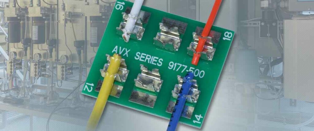
- Test and Measurement – Replaceable connectors allow various instruments like multi-meters and signal generators to safely interface test leads to live circuits.
Myriad applications in every industry depend on the flexibility of wire to board connectors for implementing detachable I/O interfaces.
Conclusion
Wire to board connectors enable removable electrical connectivity from cables to PCBs in countless electronic devices and systems. Their modular nature supports field servicing, flexible assembly, and product upgrades over time. However, designing connectors that withstand mechanical stresses and environmental conditions to achieve target lifetime requires material science and engineering expertise.
With increasing demands for data rates and connectivity, advancements continue in wire to board connectors and associated PCB layout practices. Engineers must balance high-speed signal integrity, power density, manufacturability, and cost when specifying appropriate connectors. Used judiciously, wire to board connectors empower maintainable, evolvable electronic system architectures.
Frequently Asked Questions
What are typical steps to design wire to board connectors into a system?
- Estimate needed density, voltage, current, and environmental ratings based on system requirements
- Research suitable connector families and components based on constraints
- Create initial connector and PCB land pattern footprints with supplier CAD models
- Simulate electrical performance like impedance matching if high speed signals
- Prototype connections to validate mechanical and electrical functionality
- Perform environmental stress testing – thermal cycling, vibration, etc.
- Iterate on design as needed to pass qualification requirements
How are wire to board connectors specified for high frequency signals?
Precision impedance matched connectors would be utilized. This may entail wire to board coaxial connectors combined with PCB controlled impedance routing, dielectric material selection, and simulations to match impedances across interfaces.
What are some key considerations for connector placement on a PCB?
- Accessibility for mating/unmating – clearances for tools, hands, etc.
- Clearance from housing walls and internal components
- Separation from heat sources that may impact temperature rating
- Mechanical stability – locating connectors in areas with minimal flexing or vibration
- Panel cutting considerations to expose external connectors like D-Subs
How can wire to board connectors be protected from dust and liquids?
- Specify connector housings or plugs with sufficient IP rating for the environment
- Use caps or covers to protect unmated connectors
- Apply conformal coating around connector region
- Heat shrink or potting material around cable junction
- Avoid exposure to contamination during handling and installation
What testing validates wire to board connector reliability?
Typical qualification tests include temperature cycling, vibration, mechanical shock, humidity, chemical exposure, and mating durability. Connectors may undergo thousands of mating cycles to validate contact wear performance.


