Managing heat dissipation is critical for reliable printed circuit board (PCB) operation. As components shrink while power densities rise, excess PCB temperatures can quickly degrade performance and reliability. A key material property impacting heat flow is thermal conductivity – the rate at which heat travels through a substance.
Understanding thermal conductivity differences across PCB materials is essential in designing boards that effectively cool components and avoid hot spots. This guide examines the major PCB constituent materials, their thermal properties, design tradeoffs, and best practices for leveraging these differences. Read on for a comprehensive look at thermal characteristics of the core substances comprising modern PCBs.
Importance of Thermal Conductivity
Why does thermal conductivity matter for PCB performance?
- Removes heat from delicate components
- Prevents temperature overshoots
- Limits thermomechanical stresses
- Reduces leakage currents and noise
- Enables higher power densities
- Extends electronic product lifetimes
In short, materials with higher thermal conductivity maintain safe PCB temperatures for reliable operation.
Units of Thermal Conductivity
Thermal conductivity (κ) is defined as:
- Power dissipated (Watts)
- Per unit area (m2)
- Per degree temperature difference (K or °C)
Typical units:
- W/m-K (SI units)
- W/m-°C (alternative SI units)
- BTU-in/ft2-hr-°F (Imperial units)
Higher thermal conductivity indicates more heat traverses a material per given temperature difference and cross-sectional area.
Metals – Copper
Copper is the primary metal comprising PCB tracks and planes:
- Excellent conductivity – second only to silver
- κ = 400 W/m-K, 6 times more than steel
- Attractive electrical properties as well
- Ductile – easy to manufacture into foils and deposit
- Corrosion resistant when plated
- Relatively affordable
Highly suitable for heat spreading across PCBs when used for large area fills and thick plating.
Metals – Aluminum
Aluminum sees some use as a thermal PCB substrate:
- Very high thermal conductivity – κ = 230 W/m-K
- Low density – 2.7 g/cm3 vs 8.9 for copper
- Readily extruded into flat sheets and plates
- Requires insulating dielectric separation from copper traces
- CTE mismatch with copper causes stresses
Used when light weight is critical despite fabrication challenges.
Metals – Kovar Alloy
Kovar is an iron-nickel-cobalt alloy used for leadframes:
- Low thermal conductivity – κ = 17 W/m-K
- Matches thermal expansion of silicon, alumina
- Requires nickel/gold plating for corrosion protection
- High fabrication costs limit applications
Mainly used only when CTE matching to ceramics is essential.
Metal Comparison Table
| Metal | Thermal Conductivity (W/m-K) |
|---|---|
| Silver | 429 |
| Copper | 400 |
| Aluminum | 230 |
| Gold | 318 |
| Brass | 109 |
| Kovar | 17 |
| Stainless Steel | 16 |
| Invar | 10 |
Ceramics – Aluminum Oxide
Alumina ceramic sees frequent usage in PCBs:
- Very low thermal conductivity – κ = 30 W/m-K
- Electrically insulating
- Hard and wear resistant
- Withstands high temperatures
- Often used for substrate insulation
Primarily leveraged for electrical isolation rather than thermal dissipation.
Ceramics – Aluminum Nitride
Aluminum nitride ceramic has higher thermal performance:
- κ = 170 W/m-K
- Matches silicon CTE
- Electrically insulating
- Withstands over 600°C
- Carries high cost premium
Used where electrical isolation and high heat transfer are simultaneously needed.
Ceramics – Beryllia
Beryllium oxide ceramic offers the best thermal ceramics properties:
- Excellent thermal conductivity – κ = 260 W/m-K
- Electrically insulating
- High strength and hardness
- Withstands harsh environments
- Toxicity causes manufacturing challenges
- Very costly
Deployed only when thermal and electrical demands justify the risks and expenses.
Ceramic Comparison
| Ceramic | Thermal Conductivity (W/m-K) |
|---|---|
| Beryllia | 260 |
| Aluminum Nitride | 170 |
| Silicon Carbide | 120 |
| Boron Nitride | 60 |
| Alumina | 30 |
| Glass Ceramic | 1 |
Polymers – PTFE
Polytetrafluoroethylene (PTFE) is a common plastic in PCBs, used as wire insulation:
- Very low thermal conductivity – κ = 0.25 W/m-K
- Chemically non-reactive
- Withstands high temperatures
- Flexible
- Relatively expensive compared to other plastics
PTFE is leveraged primarily for its electrical and chemical properties.
Polymers – PVC
Polyvinyl chloride sees widespread use as wire insulation:
- Similarly poor thermal conductivity – κ = 0.19 W/m-K
- Low cost
- Easy processing
- Moderate temperature rating
- Undergoing phase-out due to toxicity concerns
Also employed predominantly for electrical and cost attributes rather than thermal suitability.
Polymers – Polyimide
Polyimide films serve as bonding layers in flexible PCBs:
- Slightly better but still very low conductivity – κ = 0.12 W/m-K
- Withstands high temperatures
- High chemical resistance
- Relatively expensive
- Poor thermal matching to metals causes delamination
Leveraged primarily for its electrical insulation and chemical properties.
Polymer Comparison
| Polymer | Thermal Conductivity (W/m-K) |
|---|---|
| Nylon | 0.25 |
| PTFE | 0.25 |
| Polycarbonate | 0.20 |
| PVC | 0.19 |
| Polyimide | 0.12 |
| Polyurethane | 0.12 |
| Polyester Resin | 0.10 |
Dielectrics – FR-4
Flame retardant grade 4 glass-epoxy is the standard PCB substrate:
- Very poor thermal conductivity – κ = 0.25 W/m-K
- Low material cost
- Well-characterized electrical properties
- Limited temperature range
- Prone to thermal delamination stresses
Designed for affordable electrical isolation rather than heat transfer.
Dielectrics – PTFE Composite
PTFE composites are a common FR-4 alternative:
- Marginally better thermal conductivity – κ = 0.70 W/m-K
- Reduced risk of water absorption
- Improved high temperature rating
- Increased material costs
Provides only slightly better thermal performance than FR-4.
Dielectrics – Ceramic Filled PTFE
Filling PTFE with ceramic particles boosts conductivity:
- κ increased to 1-3 W/m-K or more
- Reduces thermal expansion
- Allows higher operating temperatures
- Significantly more expensive than FR-4
- Improved but still poor heat transfer
A compromise between cost and thermal management.
Dielectric Options Comparison
| Dielectric | Thermal Conductivity (W/m-K) |
|---|---|
| Alumina | 30 |
| Ceramic-filled PTFE | 1-3 |
| PTFE Composite | 0.7 |
| FR-4 | 0.3 |
| Polyimide | 0.1 |
Solder Masks
Solder masks provide environmental protection for PCBs:
- Typical epoxy acrylic masks have very low thermal conductivity in the 0.15-0.3 W/m-K range
- Can be selectively excluded in areas requiring heat transfer
- Newer options use siloxane coatings with conductivity around 0.7 W/m-K
- Minimal improvement over standard masks
Solder masks prioritize insulation and moisture sealing rather than thermal dissipation.
Via Fill Materials
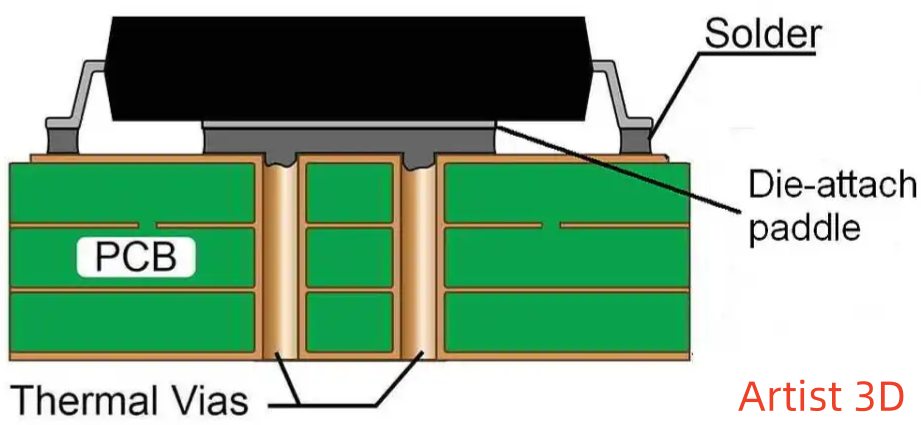
Filling empty vias improves thermal performance:
- Copper – Excellent κ = 400 W/m-K
- Silver – Unparalleled conductivity but expensive
- Solder – Reflowable κ = 50 W/m-K
- Conductive Epoxy – Nearly matches solder’s conductivity
Avoid empty voids in vias to maximize vertical heat conduction.
PCB Material Thermal Conductivity – Key Takeaways
- Metals like copper and aluminum excel for heat spreading
- Ceramics provide electrical insulation with moderate thermal conduction
- Polymers and dielectrics act as thermal insulators by design
- Small material improvements offer limited gains versus redesigned structures
- Enhance conductivity along anticipated thermal paths
Improving Thermal Performance – Guidelines
Strategies to effectively leverage material properties for cooling PCBs:
- Use thick copper weights – 2oz and above
- Specify low resin content laminates
- Request high TG laminates where suitable
- Assign critical traces to internal layers
- Use a metal substrate if power densities demand
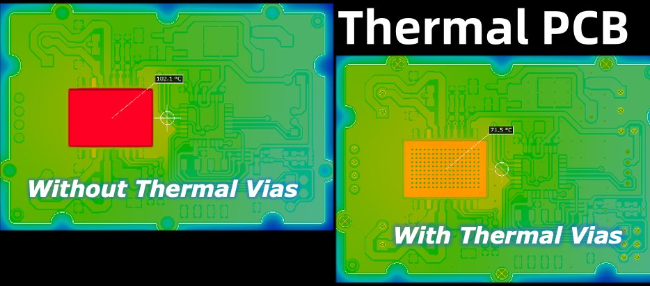
- Convert unused vias to thermal vias
- Eliminate cutouts/splits in ground planes
- Attach external heat sinks where needed
- Validate performance through thermal modeling
Design Tradeoffs
| Benefit | Drawback | |
|---|---|---|
| Thick copper | Decreased manufacturability | |
| Metal core PCB | Increased cost and weight | |
| More layers | Improved thermal spreading | Fabrication complexity |
| Low resin laminates | Enhanced in-plane conduction | Reduced out-of-plane insulation |
| Ceramic fillers | Increased conductivity | Higher material expenses |
Balance inherent material limits with tailored constructions that strategically direct heat flow.
Thermal Conductivity – FQA
How does copper plating thickness affect thermal conductivity?
Thicker plating results in a larger cross-sectional area for heat conduction, reducing in-plane thermal resistance. But the bulk conductivity of the copper itself does not change. With very thick stacks of 2 oz copper or above, the improved spreading outweighs added costs.
Do materials with higher thermal conductivity also have higher electrical conductivity?
Generally yes, as both conduction mechanisms rely on free electron mobility. Metals excel in both while plastics insulate electrically and thermally. But some exceptions exist. Beryllia ceramic has thermal conductivity comparable to metals but is electrically insulating.
How should via placement be tailored based on thermal characteristics?
Vias containing thermally conductive fills should be clustered under hot components and distributed evenly across the PCB to facilitate vertical heat transfer and spreading. Areas with vias carrying sensitive electrical signals should have thermal vias interleaved but with sufficient spacing to limit electrical interference.
Is direct metal attachment better for cooling than solder?
Bonding bare copper components directly to metal core PCBs provides marginally better interface conductance than solder. But solders are preferable for most applications, owing to ease of rework, compliance to absorb differential expansion, and thermal/electrical isolation benefits.
Should every plated through-hole be converted to a thermal via?
Making all PTHs thermal vias without regard to original function adds unnecessary cost for minimal benefit. Reserving such enhancements specifically for unused vias in hot areas achieves better results. Thermal and electrical design concerns should be weighed separately.
Conclusion
From metals to ceramics, dielectrics and polymers, the range of thermal conductivity across PCB materials spans orders of magnitude. But intrinsic material properties tell only part of the story. Optimized constructions and geometries strategically direct heat flow where needed most. With a nuanced understanding of thermal conduction principles and material strengths, PCB designs can effectively dissipate heat, satisfying both electrical and thermal functional requirements.


