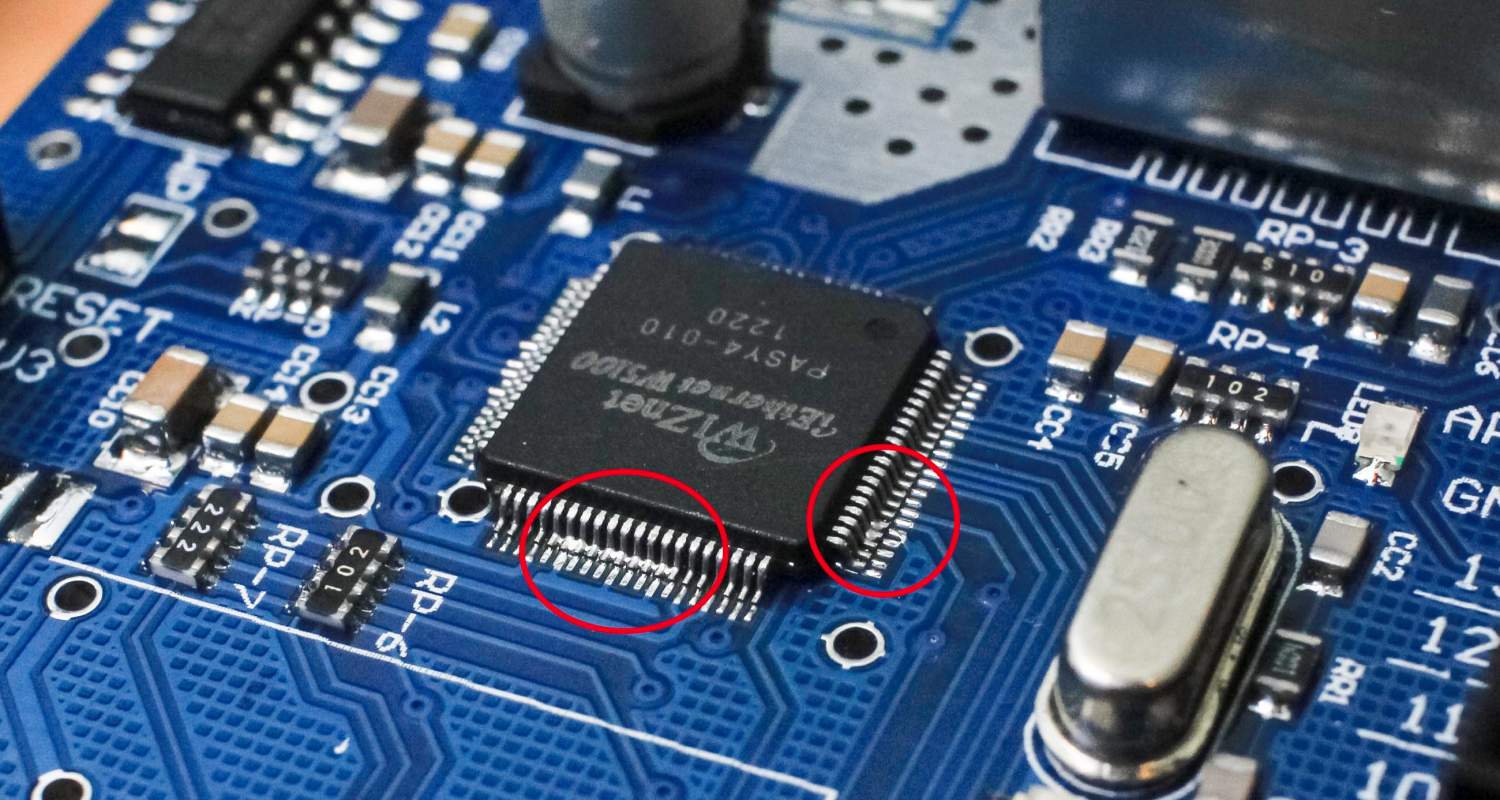
What is Solder Bridging?
Solder bridging refers to the unintended electrical connection created when solder forms between adjacent component pads, lands, terminals or conductors on a printed circuit board assembly.
This phenomena occurs as a result of excess solder spreading out from a joint during reflow soldering operations. Capillary wetting action draws the molten metal across narrow spaces between pins drafting up solder bridges which must get reworked.
Bridging Fault Examples
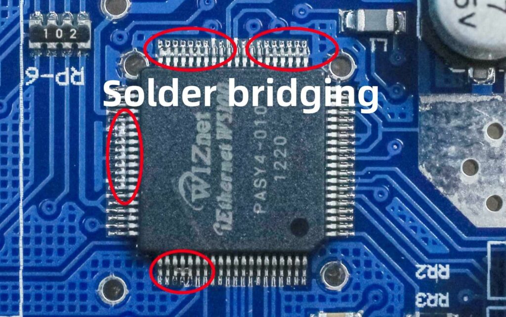
Typical locations vulnerable to solder bridge defects include:
- Fine pitch integrated circuits with dense pin spacing
- Bottom terminated components like connectors with dual rows of tabs
- Area array packages such as BGAs and CSPs
- Clustered passive elements and bypass capacitors
- Crossover traces in multi-layer PCBs
In each case, insufficient margin exists to isolate wetted solder alloy between targets resulting in shorts or impaired performance once cooled.
What Causes Solder Bridging?
Several interacting factors promote conditions allowing molten solder to spread between adjacent features during assembly soldering:
Excess Solder – Too much solder paste on pads creates bridging risks. Common from oversized stencil apertures, screen misalignment, scooping, or double prints.
Wettable Surfaces – Nearby metallic or plated regions allow solder to readily wick laterally away from deposits.
Inadequate Clearances – Narrow spacing between lands, pins or traces enables solder to easily bridge.
High Reflow Temperatures – Excess peak temperatures decrease alloy viscosity facilitating spread.
Poor Paste Release – Paste sticking to stencil apertures raises bridging likelihood.
Insufficient Anti-Solder Mask – Lack of adequate solder dams allows molten metal migration.
In practice, most bridging instances trace back to some combination of interacting solder, design and process factors overwhelming the surface tension retention within the liquidus foam trying to hold discrete coalesced droplets over individual lands.
Fundamentally however, excessive solder deposition coupled with narrow clearance gaps represents the root cause behind short circuit formations.
Bridging Prevention Strategies
With so many variables potentially contributing to solder bridging, mitigation tactics should address multiple aspects:
1. Optimize Solder Paste Printing
- Balanced Aperture Dimensions – Stencil openings mirroring the pad size minimize excess paste.
- Step-Down Stencils – Two-level masks restrict paste thickness over fine pitch components.
- Proper Alignment – Precise registration between stencil and board prevents paste transfer off pads.
- Clean Masks – Prevent paste retention around apertures.
- Revised Reflow Profile – Customized thermal recipe helps paste release while limiting spread.
2. Follow Solder Mask Design Rules
- 8-12 Mil Minimum Web Width – Narrower risks bridging through mask dams.
- 2:1 Pad Opening Size – Restricts paste volume and solder spread access.
- Global Expansion Offset – Compensates for mask misregistration.
3. Modify Pad & Circuit Layouts
- Increased Land Spacing – Wider gaps impedes capillary flow between pins.
- Leave every 3 Pin Unpopulated – Interrupt continuous solder surfaces.
- Solder Thieves – Redirects excess volumes away from densely spaced pads.
- Rounded Pad Corners – Discourage corner wetting initiation points.
4. Change Assembly Materials
- Solder Paste Alloy – Varying composition impacts viscosity, surface tension and oxides.
- Flux Formulation – Special low solids and no-clean blends resist spread.
- Pad Surface Finish – ENIG, Imm Sn, Cu-OSP affect wetting behavior.
5. Adjust Reflow Parameters
- Lower Peak Temperature – Reduces alloy fluidity.
- Shorter Time Above Liquidus – Minimizes window for flowing.
- Improved Cooling Ramp – Faster set up increases viscosity quicker before bridges solidify.
Numerous solder bridging corrective actions exist at the solder, PCB, component and process level with application depending on the specific product and defects observed.
Solder Bridge Inspection
Verifying solder joint quality requires examining assemblies for bridge occurrences and other common defects during manufacturing. This demands both automated and manual soldering inspection techniques suited for finding shorts.
Automated Optical Inspection (AOI)
Fast 2D and 3D machine vision now matches human visual inspectors identifying solder defects down to hidden shorts between bottom side BGA balls or under components.
Algorithms automatically flag bridge risks based on program parameters for inter-connect spacing and acceptable solder spread limits between adjacent pads.
Certain systems also trace runtime thermal profiles during reflow oven passage to predict and detect process deviations contributing to bridge formation like insufficient pre-heat ramps or excessive peak temperatures.
Other Solder Joint Tests
Electrical testing provides the ultimate determination of solder bridge faults throughopens and shorts checks of etched test coupons or manufactured assemblies. Continuity measurements confirm suspected bridges from optical examination.
X-ray inspection offers another advanced technique capable of screening solder joints for shorts with 2D or 3D tomography identifying hidden bridges between lands obscured underneath mounted components.
Depending on product complexity, device sensitivity, and quality criteria, a combination of AOI, x-ray, and electrical testing provides fully verification of solder bridging avoidance plus general joint integrity.
Solder Bridge Rework
Despite best efforts, some percentage of assemblies still exhibit solder bridging defects during manufacturing requiring remediation after inspection and failure identification.
Manual Soldering Iron
Basic hand soldering remains a practical method for removing isolated solder bridges.
Technicians use mini picks and vacuum desoldering tips under magnification to gently detach and suck up rogue solder streams bridged across nearby joints without damaging pads or plated through holes.
Manual rework limits part heating but risks trace tears or lifted lands needing repair if overly aggressive on fragile boards. Success depends greatly on operator skill.
Soldering Station
Air-heated tweezer tips offer better thermal control than basic irons when clearing solder bridges from populated boards. Nitrogen options further localize heating to bridge location without disturbing nearby components.
Micro soldering stations also facilitate clearing conformal coated assemblies by quickly piercing protective films to melt offending solder shorts.
Selective Solder Pot
Dedicated solder pots with adjustable lancing fountain wave height provide fast rework stations for removing bridged solder then redressing joints. Panelized boards can run through to automatically clear shorts across an entire plate.
Precise nozzle targeting and bottom side heat shields localize the strip and repair action to justproblematic areasyet risk overheating other adjacent parts not robust to total immersion baths.
Laser Soldering
Pulsed laser micro-soldering focuses high energy onto individual solder shorts severing connections without conduction spreading beyond the tightly controlled beam diameter. diode lasers or fiber lasers are commonly used.
Infrared camera attachments aid pinpoint targeting of obscured or hidden solder bridge locations under live components. No fluxesrequired prior to lasing.
Laser rework offers unparalleled precision with limited collateral heating suited to repairing bridged solder on extremely dense electronics.
Preventative Production Practices
Besides reactively fixing boards with solder bridges, SMT assembly lines should instigate preventative measures ensuring process capability and control limits bridge occurrences through improvements like:
| Process Step | Bridging Prevention Practices | |
|---|---|---|
| Solder Paste Mixing | – Controlled atmosphere mixing <10% RH <22°C | |
| – Monitoring viscosity and tack life | ||
| – X-ray analysis checks powder size distribution | ||
| Solder Paste Printing | – Vision alignment systems | <0.100mm Cpk |
| – Stencil cleanliness verification <10 defects per panel | ||
| – Automated stencil roll printers | ||
| PCB Handling | – Eliminating condensation drip or contamination onto fluxed pads | |
| Reflow | – Minimum 100°C/second heating after soak zone | |
| – Maximum 15 seconds solder liquidus stage | ||
| – Forming gas or nitrogen atmosphere | ||
| – Thermal process optimization with test vehicles |
Likewise, statistical quality control tracking helps characterize production performance measuring short term process variability against control limits and capability indices like Cpk.
Data trending then aids diagnosing issues while guiding corrective actions necessary to meet solder bridging quality benchmarks.
FQA
What is meant by solder bridging on circuit boards?
Solder bridging refers to unintended electrical connections formed when molten solder spreads laterally across narrow gaps and shorts between adjacent metallic pads, lands traces or component leads during reflow soldering assembly operations due to phenomena like capillary wetting action.
What design factors contribute to solder bridging risks?
Insufficient spacing and solder dams between lands/terminals, excess solder paste deposits, poorly defined solder mask barriers, wettable nearby secondary surfaces, rounded pad geometries, and lengthy high temperature reflow exposure all enable bridge development.
Should solder bridging always get reworked?
If electrical tests or inspection confirms solder is shorting between distinct circuit nodes then reworking the assembly is mandatory to avoid impaired performance or field failures from the unintended connections.
What methods fix solder bridge defects?
Common rework tools include manual soldering irons, hot gas stations, selective solder pots, and laser desoldering but all require skilled operators to remove excess solder without lifting pads or damaging components. Rework difficulty scales with bridge location and surrounding part density.
How can process adjustments help avoid solder bridging?
Reflow profiling refinements like faster ramps, lower peak temperatures, and shorter exposure around solder liquidus targets help resist bridging while solder paste controls, vision alignment systems, and stencil cleaning maintenance improve transfer consistency.


