
Receptacles in a printed circuit board (PCB) refer to the connectors and sockets that interface with external plugs and components. These allow detachable links between the PCB circuitry and cables/modules delivering signals, data and power.
Common receptacle types found on PCBs will be explored along with their typical applications, advantages and installation considerations when including as part of PCB assembly.
Overview of Receptacles Role
Also referred to as female connectors, PCB receptacles fulfill several key roles:
1. Modularity
Receptacles permit field replaceable parts or connections. This aids servicing with plugin modules.
2. Cable Interfacing
Allow external wiring to deliver signals or bus standards like USB between PCB subsystems and external devices.
3. Stacking
Guide mating between layered PCBs electrically and mechanically.
4. Power Input
Receptacles simplify providing various voltage feeds onto boards.
Their flexibility comes at the expense of complexity in integration and testing.
Next we will explore common receptacle types seen on PCBs and where used.
Common Receptacle Types
Diverse interconnection needs led to an array of standardized connector and socket solutions:
Board to Board Stacking
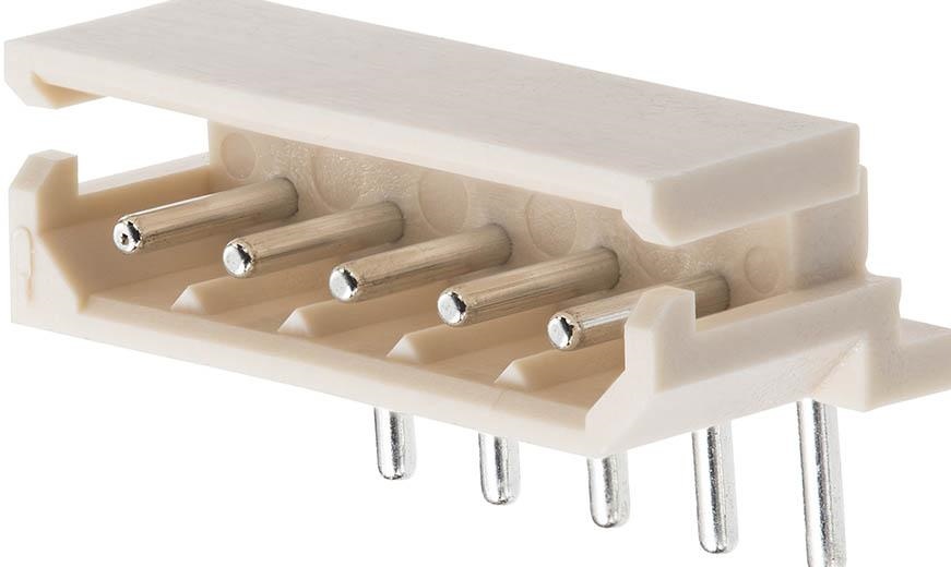
Pin Headers
Vertical pins soldered onto PCBs slot into a shrouded mating connector. Allows layering PCBs together like expansion cards.
Board to FPC
ZIF FPC connectors with locking cam squeeze contact pads against flexible printed circuit cables. Withstands vibration.
External Cable I/O
USB
Type A/B connectors interface to standard USB cables using molded insulation displacement contacts.
RJ45
Tab down sockets crimp onto Ethernet patch cables. Various grades handle Cat 5 through Cat 7.
HDMI
Snap in through-hole plastic housing secures metal contact shrouds mating with HDMI plugs.
Power Inputs
Barrel Jacks
Solder pots incorporate barrel jack housing for DC power plugs. Widespread on portable devices.
AC Power Socket
Single, double or triple plastic-housed contacts designed for AC line voltage mains power blades. Safety agency ratings.
Automotive
Plastic and metal tab down receptacles suit harsh automotive cabling. Withstand shock/vibration.
Comparison Between Families
Receptacle categories have intrinsic differences:
| Parameter | Inter-board | Cable I/O | Power Input |
|---|---|---|---|
| Pitch | 1mm – 2.54mm | >2.54mm | >5mm |
| Current | < 5A | < 3A | >10A possible |
| Retention | Friction, jackscrews | Plastic Latches | Screw flanges |
| Contact type | Stamped pins | Insulation displacement | Machined tabs |
| Termination | TH pins | TH/SMT Tabs | Solder pots |
Fine pitch inter-board connectors maximize contact density and modularity between tightly coupled subsystems. Larger power and rugged cable applications demand heavier duty parts.
Next we examine the anatomy behind a receptacle.
Receptacle Components
Key elements making up a connector on PCB side:
Molding
Plastic housing around metal contact providing insulation and mechanical mating/latching features.
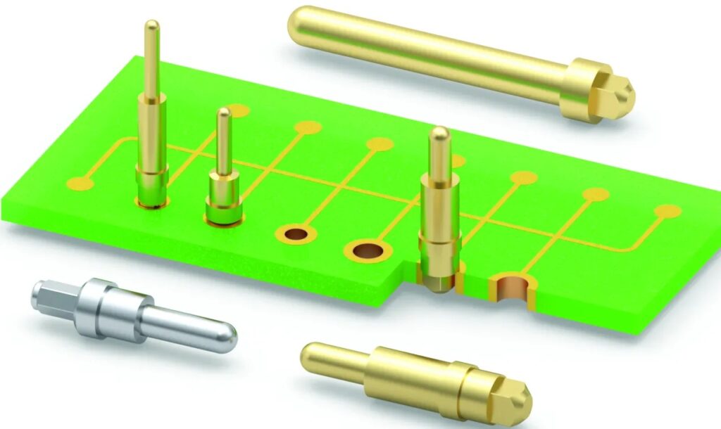
Contacts
Metal tabs or stamped pins make sliding electrical connection with mated plug. Brass/phosphor bronze are common materials offering good conductivity and spring properties. Gold, palladium or tin plating resists corrosion.
Contact types include:
- Insulation displacement – Slice through wire insulation to contact core conductor
- Crimp termination – Captures stripped wire ends within a metal sleeve using pressure
- Solder termination – Pins or tabs wetted by solder paste reflow attaching to PCB pads below
Termination
Solder pads on PCB form both mechanical and electrical connection. May be plated through hole or specialized SMT footprints. Careful pad design prevents solder wicking.
Keying
Shaping of housing and shrouding ensures plugs mate with correct orientation only. Polarization prevents improper insertion.
Example USB receptacle anatomy highlighting key elements
Moldings, contact metallurgy and termination approach varies across standards and vendors. But all aim to maximize usability, durability and reliability in application environments.
Manufacturing Defect Risks
Although receptacles appear simple, achieving robust, long lasting performance requires avoiding defects during fabrication and assembly integration:
| Defect Mode | Cause | Effect |
|---|---|---|
| Insufficient solder | Process parameters/inspection | Intermittent connections |
| Short circuits | Solder bridges or contact misalignment | Equipment failure |
| Contamination | Handling exposure of contact surfaces | Interference with signal integrity |
| Cracked components | Thermal or mechanical strain | Broken circuit under vibration |
| Wicking | Excessive solder volume | Reduced isolation to case |
Mitigations include:
- Matching thermal mass between contacts & PCB to minimize differential thermal stresses from soldering heat.
- Corner filleting and notch filling analysis during inspection catches bridging risks.
- Protective handling procedures for assembly transport.
- Simulation models predicting fatigue life and maximum strain tolerance.
While receptacles ease end user upgrades, their integration complexity demands extensive verification to attain production quality targets.
Next we explore receptacle PCB layout considerations.
Layout Design Guidance
Careful layout design improves manufacturability of board-mounted connectors:
1. Isolate circuits
Separate grounds and power planes under receptacles avoid coupling noise between circuits interacted via the connectors.
2. Ensure clearance
Check connector height relative to case enclosure depth avoids collisions when mated.
3. Facilitate inspection
Group connectors together with open access regions simplifies visual checks finding solder defects under bodies.
4. Support part proximity
Group nearby passive components in clusters around connectors minimizing trace lengths. eg USB port ferrite beads.
5. Verify port grouping
Stagger adjacent port rows mechanically avoiding housing clashes between matings.
6. Allow positioning tolerances
Size pad spans generously larger than tab/pin footprints enabling slight placement variations accommodation movement before solder lock.
7. Include alignment features
Add polarized asymmetric shaping matching receptacle and case cutouts preventing faulty rotations.
8. Simplify mating access
Position ports matching case cutout shape and orientation. Avoid narrow corner placements impeding cable bend radii.
These design choices streamline error free production assembly and subsequent servicing during product lifetime.
Next we explore disciplined receptacle integration and validation practices raising first pass success rates when deploying onto complex boards.
Integration Best Practices
Some key areas to address for reliable connector inclusion:
Firmware Detection
Code device presence detection, health checks and failure handling early via assigned controller pins. Confirms software-hardware interface readiness before release.
Design Collateral
Create 3D models, assembly drawings markups and integration notes captured in central repository shields production bring-up knowledge from individual loss.
Process Guidelines
Generate assembly work instructions e.g outlining manual inspection/rework steps with pass/fail criteria outside automated optical inspection capabilities.
Test Coverage
Expand functional test coverage scenarios to activate typical and corner case connector usage modes – confirming robustness prior to customer encounters.
Selective Volumes
Quality assurance applies extra sampling rates for connector soldering and dimensional checks during initial volumes guarding against latent defects entering field.
Application Validation
Reprduce environmental stress testing matching customer use conditions – eg automotive temperature cycling, vibration, humidity exposure etc
While adding overheads, contractor manufacturing transitions are greatly smoothed through upfront validation investments ultimately avoiding costly product returns.
Connector Failure Modes
Being electromechanical items exposed to usage stresses, connectors can fail both electrically and mechanically over product lifetime.
Typical failure modes include:
Electrical
- Fretting corrosion causing intermittent continuity
- Metal whisker growth inducing leakage between circuits
- Solder joint thermo-mechanical fatigue cracking due to cycling temperature swings
Mechanical
- Contact misalignment from repeated mating insertions
- Degraded retention strength allowing partial disengagement
- Contamination build up increasing mating force difficulty
Mixed
- Vibration induced relative motion causing fretting wear
- Accidental bending damage cracking solder joints
- Repeated current overload eventually degrading metallurgy
Most issues emerge over long term environmental exposure. But design analysis, materials selection, protective coatings and production process controls mitigates risks.
Design Analysis
Analytical validation provides confidence prior to committing expensive fabrication iteration cycles:
Thermal Simulation
Confirm heat sinks adequately dissipate connector self heating and prevent nearby component overtemperature during worst case sustained loads.
Vibration Modeling
Use finite element analysis predicting resonant modes and confirming connector securing methods survive transportation and lifespan vibration exposure without cracking solder joints or structural fatigue.
Environmental Test Correlation
Relate model predictions to results from industry standard qualification tests through parameters like derating safety factors and failure distributions. Refine models accordingly.
Such modeling sharply reduces product development costs over empirical reliability testing alone. But measured results still necessary validating simulations reflect true system interactions.
Connectorization Tradeoffs
Increasing use of connectors aims to improve flexibility but comes with downsides to weigh:
Benefits
- Field replaceable modules
- Signal interface standardization
- Stacked daughterboards
- End product customization
Costs
- Additional components and integration complexity
- Extra failure risk points
- Manual assembly time overhead
- Special fixture requirements
- Case cutouts and clearance
Project constraints determine suitable connectorization level ranging from minimalist glued peripherals through to internally stacked architecture with field replaceable plugins. The higher serviceability comes at a cost premium.
Future Directions
Interconnection requirements continue advancing requiring connectors evolve apace:
Pitch Scaling
Component density keeps rising demanding fine pitch connectors avoid compromising modularity and serviceability.
Signal Integrity
Faster edge rates require impedance matched contacts and careful equalization at >25+ Gbps speeds.
Power Delivery
Higher currents mandate intelligent power connectors to safely negotiate voltages keeping resistance minimal.
Environmental Resistance
Harsher temperature, chemical, humidity, corrosion exposures need improved sealing and metallurgy.
Simplified Human Interfaces
Reducing servicing complexity improves customer experience and minimizes incorrect equipment damage from human error.
Connector solutions rising to these demands enable next generation electronics meet reliability expectations across an expanding range of deployment scenarios.
Conclusion
Receptacles fulfill indispensable roles on PCBs allowing field customization, cabling interfaces and interconnection between modules. Careful connector selection, integration and validation unlocks benefits of modular designs while controlling cost and quality risks – especially important for long lifetime applications spanning consumer through automotive domains.
Advancement in analytical modeling also allows improving connector reliability continuously during development rather than depending solely on prolonged validation testing – shortening product launch cycles dramatically.
The expanding connector families and ongoing technology improvements continue meeting demands of rising electronic performance and robustness needs across application segments.
FAQ
What are the most common types of connectors used on PCBs?
Most prevalent receptacles integrated on printed circuit boards are board-to-board pin headers, flexible ribbon cables, USB ports, RJ45 Ethernet jacks and DC power barrel connectors. Their pitch, retention and contact types vary widely suiting interconnect needs.
What design risks occur with board-mounted connectors?
Insufficient solder, bridging shorts between contacts, wicking up solder mask and thermal expansion cracks are common defects degrading connector reliability. Careful specification matching parts to PCBs, inspection checklist expansion and modeling tolerance stacks helps mitigate risks.
What information should design collateral include for connectors?
Connector integration collateral accelerates production readiness comprising datasheets specifying mechanical/electrical parameters, 3D models aiding case clearance checks, detailed installation drawings, soldering process guidelines and any special rework tools necessitated.
How is vibration resilience ensured for connectors?
Vibration can compromise solder joint integrity over time from relative shearing motion. FEA simulation models board flexure effects determining maximum acceleration tolerance for the mounting method. Additional underfill epoxy may be used for reinforcement where needed.
What future connector improvements help ongoing electronic systems?
Ongoing connector developments target finer pitch for density and modularity, improved signal integrity for high speed interfaces, upgraded power delivery ratings, better resilience to challenging operating environments through advanced sealing as well as simplified, foolproof user mating and handling.


