Introduction to PTFE Printed Circuit Boards
PTFE, also referred to as Teflon, is an advanced printed circuit board (PCB) substrate material prized for exceptional thermal, electrical and mechanical attributes. PTFE laminates establish reliable foundations for demanding applications with strict electronics packaging constraints across automotive, aerospace, 5G infrastructure, phased array radar and other fields.
This article explores PTFE PCB technology covering:
- PTFE attributes and advantages
- PCB material selection priorities
- PTFE formulations and alternatives
- Fabrication considerations
- Reliability impacts
- Cost tradeoffs
Reviewing key properties that position PTFE as an elite circuit substrate aids both design decisions and driving next-generation innovations relying on uncompromising PCB material performance at extremes of environment.
Overview of PTFE Polymer Properties
Polytetrafluoroethylene (PTFE) was discovered serendipitously in 1938 by a frustrated chemist perplexed by a failed experiment. Today the world ubiquitously knows PTFE as non-stick Teflon coating kitchenware.
So why is relatively obscure PTFE crucial for intricate electronics?
Key Electrical Properties
PTFE exhibits invaluable electrical behavior:
- Extremely low dielectric loss enabling high frequencies
- Low dissipation factor (high Q factor) boosts signal quality
- Near constant dielectric constant across broad spectra
- Highest resistivity of any commercial polymer
- Negligible signal cross-talk ideal for tightly packed layouts
These attributes sustain pristine wave propagation critical in RF systems.
Robust Mechanical Attributes
PTFE delivers resilient physical integrity:
- Operable over {-100°C : 260°C} span
- Chemically inert to practically all solvents
- Weather/corrosion proof in harsh conditions
- Withstands intense radiation without damage
- Non-stick surface easily cleaned
Ruggedness permits deploying PTFE PCBs in punishing environments.
Diverse Application Suitability
Superior electrical and mechanical pedigree coupled with chemical resistance allows PTFE adoption across electronics sectors:
| Industry | Application | Operating Conditions |
|---|---|---|
| Aerospace | Avionics systems | Pressure, vibration, fuels/fluids exposure |
| Automotive | Engine controllers | Temperature cycling, humidity, fluids |
| Chemical Processing | Instrumentation | Corrosive substances, high temps |
| Energy | Well logging sensors | High ambient temps, pressures |
| Defense | Radars, guidance | Extreme vibration, altitude, reliability mandates |
PTFE empowers electronics engineers pushing boundaries.
Next we’ll zoom deeper into driving priorities when selecting PCB substrate materials before highlighting additional PTFE formulations.
PCB Material Selection Priorities
Material sciences furnish a diverse PCB substrate palette suiting varied applications. Manufacturers characterize laminates across electrical, mechanical, chemical and thermal quantitative metrics allowing intelligent material selections aligned with product goals during design phases.
Top Electronics Material Properties
| Property | Description | Units | Importance |
|---|---|---|---|
| Dielectric Constant (Dk) | Charge storage capacity | Unitless | Radio frequency performance |
| Loss Tangent (Df) | Energy wasted as heat | Unitless | Limits signal speed/quality |
| Coefficient of thermal expansion (CTE) | Thermal expansion rate | ppm/°C | Compatibility across temperatures |
| Glass transition temperature (Tg) | Softening onset temp | °C | Upper operable bound before deforming |
| Decomposition temp (Td) | Chemical breakdown beginning | °C | Sustained thermal limit for polymer longevity |
| Young’s Modulus | Stiffness, rigidity | GPa | Susceptibility to bending, vibration issues |
| Moisture absorption | Water weight gain | % | Tendency to uptake ambient humidity |
| Z-axis expansion | Layer separation forces | % | Interlaminar stresses during fabrication |
Note: Additionally important but omitted for brevity: flammability, fracture toughness, tensile strength and volume resistivity.
Evaluating quantitative polymer metrics against reliability, lifespan and functionality prerequisites identifies ideal candidate PCB materials optimally fulfilling specialized niches, as we’ll discuss regarding versatile PTFE.
PTFE Formulations and Composites
While pure PTFE boasts laudable natural properties, injection molding difficulties motivate creation of composites and fillers improving manufacturability plus enhancing thermal/mechanical characteristics:
| Variant | Description | Typical Fillers | Benefits | Applications |
|---|---|---|---|---|
| Glass-reinforced PTFE | Particulate glass fibers | 15-25% glass fabric | Improved Z-axis strength, machinability | Microwave boards |
| Ceramic-filled PTFE | Ceramic particle inclusion | Silica, alumina and titania | Higher dielectric constant tunability, stiffness | Antenna substrates, space/satellite |
| Fiber-filled PTFE | Small oriented fiber mix | Carbon, graphite, fiberglass, aramid | Lower CTE, improved dimensional stability | High speed digital, wireless infrastructure |
| PTFE composites | Blended with thermoplastics | PEEK, LCP, PPS, PAI | Balancing electrical performance against cost | Automotive radar, telecom |
Modifying PTFE with fillers or reinforcing components caters to economic constraints and fabrication limitations associated with pure formulations.
Now that we’ve covered PTFE properties and varieties, next we’ll examine manufacturing technology considerations.
PTFE PCB Fabrication Notes
Harnessing exceptional electrical functionality possible with PTFE requires mastering fabrication techniques addressing associated manufacturability challenges.
| Fabrication Step | Procedure | Difficulties | Mitigations |
|---|---|---|---|
| Etch patterning | Photolithography masking, chemical etchant baths | Poor adhesion of photoresist, handling thin cores | Modified liquid etchants, custom double-sided processes |
| Oxide treatment | Plasma surface activation | Susceptibility to cracking with standard glassification | Lower energy plasma cycles |
| Layer lamination | Stacking up cores/prepregs, thermal pressure bonding | Low surface energies hamper adhesion | Specialized adhesives, etched surfaces |
| Drilling | Mechanical drilling through substrate stack | Smearing, poor hole wall quality | Optimized feeds/speeds, vapor honing |
| Metallization | Conductive interfacing, plating | Seeding adhesion before plating | Micro-roughening, special adhesion promotors |
| Assembly | Component population, reflow soldering | Sensitivity to thermal shock extremes | Preheating before reflow, customized temperature profiles |
Fabricators invest heavily in precision machining, customized tooling and process refinement expertise necessary translating PTFE’s elite electrical virtues into end application reality.
Next we’ll analyze factors impacting manufactured PTFE PCB reliability across operating lifetimes.
Considerations for PTFE PCB Reliability
While alluring on paper, amortizing benefits of PTFE PCB technology mandates delivering robust long term reliability:

Common failure modes:
- Interlayer delamination
- Copper cracking
- Poor intermetallic formation
- Thermal stress fractures
- Surface pitting
Lifetime maximization requires:
- Stringent handling procedures
- Eliminating residues
- High purity materials
- Smooth chemistry transitions
- Hermetic sealing
- Appreciating crack propagation kinetics
Mission critical electronics demand comprehensive reliability assessment quantification through thermal cycling, mechanical shock/vibration, moisture/bias testing and other accelerated lifetime testing methodology stressors reflecting deployment conditions.
This ensures latent defects or degradation precursors surface well before field deployment allowing corrective actions. PTFE printed boards thus require additional scrutiny over conventional FR-4 counterparts.
Finally let’s weigh economic tradeoffs associated with specialized PTFE PCB technology.
Cost Considerations for PTFE Printed Circuit Boards
Surpassing reliability and functionality milestones ultimatelynecessitates examining associated costs for economic viability:
PTFE Cost Drivers:
- Raw materials: Resins multiple times conventional laminates
- Special handling: Controlled environment protocols
- Advanced processes: Customized fabrication steps
- Low volumes: Limited market size inability capturing scale economies
- Scrap rates: Tighter tolerances shrink yields
- Certifications: Extensive regulatory testing
- IP royalties: Licensing fees to materials suppliers
Aggregating overheads across supply chain magnify end pricing for electronics OEMs prioritizing performance. Weighing quantifiable quality, reliability and lifetime value versus higher upfront component acquisition costs allows intelligent cost benefit analysis guiding adoption.
Now we’ll cover common PTFE PCB questions.
Frequently Asked PTFE PCB Questions
Q: Does PTFE laminate need special storage or handling?
Yes! To prevent moisture absorption issues, PTFE materials demand storage in sealed metallic bags with desiccant packs and humidity indicators. Before use, allow controlled adjustment to ambient workshop conditions to prevent condensation-induced defects.
Q: Can you solder to PTFE boards?
PTFE requires specially adapted solder masks, metallization and preparations for component tinning and solderability. Fluorinated ethylene propylene (FEP) makes suitable smooth solder masks. Ensure fabricators understand PTFE boards’ unique requirements.
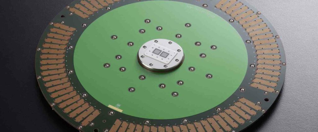
Q: What types of antennas use PTFE laminates?
PTFE’s stability across temperature fluctuations paired with low loss traits at high frequencies make it ideal for aerospace radar domes, 5G base station phase array antennas and satellite communication links needing precision dielectric constants.
Q: Does PTFE laminate need special disposal or recycling?
Handling scrap PTFE does demand safety precautions due to toxic decomposition byproducts when incinerated including hydrogen fluoride and carbonyl fluoride gases. Disposal should follow regional hazardous material regulatory mandates. Recycling options are limited.
Q: Can you laser drill microvias in PTFE PCBs?
CO2 lasers paired with graphite assisted drilling optimize microvia construction in PTFE printed boards, though demands process refinements compared to conventional materials. Maintaining acceptable taper angles and avoiding resin smear are considerations.
Conclusion
This exploration of PTFE PCB technology spanning materials science, fabrication, reliability and cost factors demonstrates why polytetrafluoroethylene remains cherished for electronics pushing radiofrequency speed frontiers.
Unparalleled low loss traits drive PTFE adoption where signal integrity reigns despite economic overheads and supply chain complexities. When application performance merits no compromises, designers count on PTFE printed circuit boards delivering unflinching stability under extremes of stress, temperature and environmental duress well into the future.
So while largely unseen, ultra-reliable PTFE substrate enables everyday advances from radar speed gun tickets to satellite TV and GPS wayfinding plus countless industrial applications benefiting society.


