
Introduction
Drilling is a critical step in printed circuit board (PCB) manufacturing that creates the holes used to mount and interconnect components on the board. Holes allow attachment of through-hole parts, routing of signals between layers, proper alignment, and securing boards in assemblies.
In this comprehensive guide, we examine:
- The PCB drilling process sequence
- Common hole types and their purposes
- Key drill bit styles and materials
- Characteristics of precision drilling machines
- How to select optimal drilling equipment
- Factors that impact hole quality
- Latest innovations in PCB drilling technology
Understanding the drilling process empowers PCB designers, fabricators and assemblers to achieve more consistent high-quality holes that enable robust electronic products.
Overview of PCB Drilling Process

PCB drilling typically involves computer numerical control (CNC) machines using high speed drill bits to cut holes at precisely defined locations based on CAD data. The sequence comprises:
1. CAD Design
- PCB layout software used to design circuit and define drill hole locations
- NC drill files generated with hole positions and sizes
2. Panelization
- Individual PCB designs arranged on larger panels for mass production efficiency
- Software optimizes placement to maximize panel utilization
3. Drilling
- CNC machine drills holes in panel based on NC drill file
- Different bits used based on hole size and tolerance needs
- Depth of drills computer controlled for blind/buried vias
4. Deburring
- Remove burrs and debris from hole walls
- Prevents issues during plating and insertion of components
5. Metal Plating
- Electrolytic copper plating builds up conductive barrel in holes
- Provides electrical connectivity between layers
6. Hole Wall Preparation
- Processes like plasma etch clean hole walls prior to plating
- Promotes adhesion of copper to the laminate
7. Panel Singulation
- Individual PCBs separated from larger panels
- Completed using routing, scoring or breakaway tab designs
High performance drilling is crucial for enabling dense, reliable PCB assemblies.
Types of Holes Drilled in PCBs
PCBs use various types of holes and vias tailored to their function:
Through Holes
- Drilled completely through the PCB from top to bottom side
- Allow insertion of leaded components like resistors, capacitors, connectors
- Require conductive plating for electrical continuity
Blind Vias
- Extend from outer layer and stop before reaching the other side
- Connect outer layer to inner layer pads and traces
- Plated barrel provides interconnection
Buried Vias
- Located between inner layers without connecting to outer layers
- Provide direct vertical connectivity between inner layer pads
Thermal Relief Pads
- Array of small holes around component leads
- Improve solder joint reliability by reducing thermal stresses
- Allows solder wicking into pad for better heat dissipation
Mounting Holes
- Larger diameter holes, sometimes with pads
- Allow insertion of screws or bolts to mount PCB assemblies
- May be plated or non-plated depending on function
Fiducials
- Smaller precise holes at strategic locations
- Used by assembly machines for accurate alignment
Testpoints
- Plated through holes allowing temporary probing of signals
- Facilitate validation, debugging and programming of boards
Breakaway Tabs
- Small holes connecting individual PCBs in panel
- Allow singulation after depanelization
Heat Sink Clearance Holes
- Holes providing space for heat sink attachment
Careful selection of hole types enables routing, anchoring, alignment and heat transfer in the final circuit board assembly.
PCB Drill Bits Types

PCB drilling utilizes specialty drill bits tailored for high tolerance hole boring in fiberglass laminates. Common types include:
Standard Jobber Length Twist Drills
- Single flute general purpose twist drills
- Available in diameters from 0.1 mm to 3.2 mm
- Low cost but higher runout compared to other drill types
Double Flute Drills
- Two flutes impart better chip control and heat dissipation
- Minimal runout for applications down to 150 μm hole diameter
- Provides good throughput and hole quality
Micro Drills
- Three and four fluted designs for micro vias and holes below 150 μm
- Very tight diameter and runout tolerance
- Frequently used for HDI boards requiring small laser drilled blind vias
Candlestick Drills
- Long narrow drill construction for high aspect ratio holes
- Enables drilling depths up to 25x diameter
- Used where blind/buried aspect ratios exceed 10:1
Stanley Step Drills
- Can drill a range of hole sizes in graduated steps
- Allows progressively larger holes without bit changes
- Quick hole size prototyping and adjustment
Carbide V-Point Drills
- Sharper cutting edge created by v-shape tip
- Minimal damage and fraying around hole perimeter
- Excellent for hole quality in soft laminates like PTFE
Bit cost increases with tighter diameter tolerance and runout specifications needed for high density interconnect (HDI) boards. But they enable features like microvias not possible with standard jobber bits.
Key Drill Bit Materials
Drill bits for PCB drilling are fabricated using tool steel or tungsten carbide:
High Speed Steel (HSS)
- Alloy tool steel heat treated to high hardness
- Lower cost, sufficient for standard thickness FR-4 drilling
- Grades include M2, M35, M42 with hardness up to 68 HRC
Cobalt Steel
- HSS alloyed with 8% cobalt for increased strength
- Can be run at higher speeds than standard HSS bits
- Maintains cutting edge longer resulting in lower cost per hole
Carbide Tipped
- High speed steel core plated with thin layer of carbide on cutting tips
- Carbide provides sharper edge and higher wear resistance
- Used for boards requiring tight hole tolerances
Solid Carbide
- Entire drill bit body made from tungsten carbide
- Maximum hardness, heat resistance and edge sharpness
- Allows highest hole quality along with faster feed rates
- Most expensive but longest lasting if properly managed
Carbide drills offer the best lifetime and hole quality, especially for blind microvias, but have higher initial cost. HSS is adequate for less demanding boards.
Key Drilling Machine Specifications

Precision computer numerical control (CNC) drilling machines used for PCB production are characterized by:
Spindle Speed
- RPM rating from 6,000 to 160,000+ RPM
- High speeds allow faster feed rates and throughput
- Precision air bearings in spindle nose for minimal runout
Drill Bit Shank Size
- Varies from 3.175mm to 2.381mm
- Smaller shank bits allow finer hole size/pitch
- Collet size must match drill shank
Minimum Hole Size
- The smallest achievable hole diameter
- Below 100 μm possible with micro drills
- Small holes allow greater routing density
Hole to Hole Accuracy
- Placement accuracy relative to CAD data
- Tight tolerances critical for via interconnects
- In the range of 25 – 50 μm for precision drilling
Hit to Hit Accuracy
- Measure of hole size variation
- Consistency optimizes assembly yield
- Below 15 μm achieved on advanced machines
Table Size
- Dimensions determine maximum panel size
- Can range from 18” x 24” up to 30” x 40” or more
- Bigger tables allow higher throughput per run
Advanced machines like the Excellon A5 achieve high accuracies down to 0.0008” (20 microns) along with best-in-class edge quality for HDI processing. But they come at a higher cost which can be justified for critical applications like aerospace, medical and telecom.
Key Factors Impacting Drilled Hole Quality
Achieving excellent hole quality requires controlling several interdependent parameters:
Drill Bit Tolerances
- Diameter variation and runout accuracy
- Tighter the tolerances, better the hole consistency
Spindle Runout
- Radial errors in spindle collet or bearings
- Translates into poor hole position and walls
Cutting Parameters
- Feed rate, spindle speed and peck depth
- Optimized to bit style and material being drilled
Cutting Fluids
- Coolants lubricate and flush debris from holes
- Reduces friction and temperatures for cleaner walls
Drill Wear
- Gradual wearing of drill tips over time
- Reduces cutting efficiency and hole precision
- Bit resharpening or replacement interval crucial
Panel Rigidity
- Deflection under cutting forces degrades precision
- Tooling including backer plates improves rigidity
Debris Management
- Timely debris clearing prevents recutting
- Vacuum systems,Collector, bottoms.
Operator Skill
- Improper machine setup and quality checks
- Operator training critical for best practices
Pre-drill Panel Preparation
- Processes like plasma etch improve adhesion
- Leads to cleaner hole walls during drilling
Holistic control of these factors allows economical production of boards with thousands of ultra-precision holes.
How to Select Drilling Equipment for PCB Production
Choosing the optimal drilling machines for a PCB shop involves these considerations:
Throughput Requirements
- Match machine capacity to volume needs
- Spindle speed, hit times, table size all impact throughput
Hole Sizes and Tolerances
- Standard or micro-drills? Hole density?
- Tighter tolerances need more advanced capabilities
Board Materials
- Thick or thinner laminates? Soft or glass-reinforced?
- Affects suitable feed speeds and drill types
Board Complexity
- Simple double-sided vs. fine pitch HDI stackups
- More layers and higher density need precision drilling
Quality Standards
- Do holes require smooth low-defect walls?
- Is tapering or precision location essential?
Future Flexibility
- Support evolving board technology like flex, rigid-flex?
- Plan for forthcoming designs, capabilities
Total Cost of Ownership
- Machine cost vs operating costs like tooling, maintenance
- Balance investment against business demands
Available Production Space
- Clean room rating? Floor loading limits?
- Ensure adequate space for machine, maintenance access
Analysis of current and future PCB needs guides selection of drills providing the best match of capabilities to budget.
Notable Innovations in PCB Drilling Technology
Manufacturers continue innovating drilling techniques for cost-effectively achieving denser and higher quality holes:
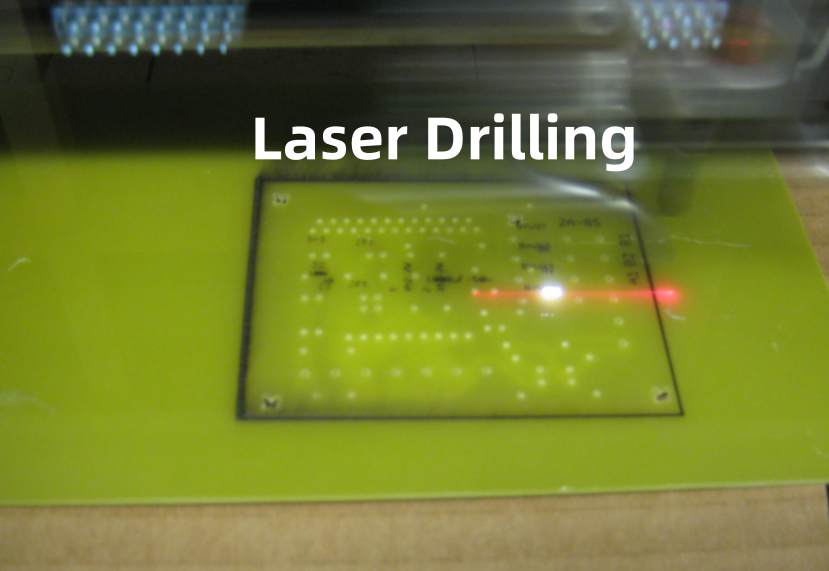
- Precise laser ablation to selectively remove laminate material
- Allows formation of microvias smaller than 25 μm diameter
- Eliminates need for cumbersome micro drills
Plasma Drilling
- Plasma beam etches hole instead of traditional drilling
- Cylindrical holes with smooth sidewalls
- No tooling wear or breakage
Atmospheric Downhole Drilling
- Fluid jetted down drill bit cleans debris
- Improves evacuation from deep micro holes
- Prevents recutting of debris
In-Cycle Probing
- Automatic measurement of drill condition
- Eliminates defects from worn or damaged tools
- Enables timely bit replacement
On-the-Fly Laser Deburring
- Directs pulsed laser to singulate panels
- Simultaneously deburrs holes
- Single seamless process step
Advanced Collets
- Flexion control and hydraulic expansion collets
- Compensate for radial errors
- Maintains hole position accuracy
By adopting such innovations, PCB fabricators can drive towards faster throughput, smaller features, and reduced costs in drilling operations.
Conclusion
Drilling creates the interconnect canvass that allows assembly of densely packed, high speed PCBs. The combination of precision drilling machines matched with optimized tooling, spindle technology, debris control, operator skill, and process settings enables the mass production of boards with thousands of extremely precise holes.
As electronics innovation marches forward, PCB drilling systems will require continuous improvement to manufacture boards supporting next generation 5G systems, high speed digital circuits, HDI, and even flex-rigid substrates. By understanding every aspect of the drilling process, engineers can make informed decisions that transform multilayer PCBs into highly functional technological wonders powering transformative products.
Frequently Asked Questions
Here are some common questions on PCB drilling answered:
Q: What are the main types of holes drilled in PCBs?
A: Common hole types include through holes, blind vias, buried vias, thermal relief pads, mounting holes, fiducials, testpoints, breakaway tabs, and heat sink clearance holes.
Q: What drill types are used for PCB hole drilling?
A: Twist drills, double flute drills, micro drills, candlestick drills, carbide drills, and step drills are commonly used depending on hole size and material.
Q: What factors impact quality and precision of drilled holes?
A: Key factors are drill runout, spindle precision, cutting parameters, tool wear, debris clearing, panel rigidity, pre-drill preparation, and operator skill.
Q: How is drilling equipment selected for a PCB production shop?
A: Based on needs like throughput, hole tolerances, board materials, complexity, quality standards, flexibility, cost and available space.
Q: What are some recent innovations in drilling technology?
A: Recent innovations include laser drilling, plasma drilling, fluid assisted drilling, in-cycle probing, on-the-fly deburring, advanced collets, and more.


