Introduction
Flex Printed Circuit Technology, also known as FPC (Flexible Printed Circuits), is an advanced form of printed circuit board technology that offers unique advantages over traditional rigid PCBs. FPCs are designed to be flexible, lightweight, and space-efficient, making them an ideal choice for a wide range of applications, including consumer electronics, medical devices, automotive systems, and industrial equipment.
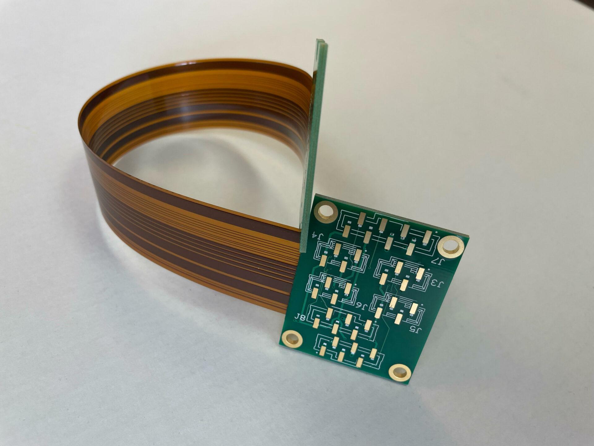
FPCs are constructed using a flexible base material, such as polyimide or polyester, onto which copper traces are etched or printed. These flexible substrates can be bent, twisted, or folded without compromising their electrical performance or integrity, allowing for compact and innovative designs.
Advantages of Flex Printed Circuit Technology
1. Space Savings and Compact Design
One of the primary advantages of FPCs is their ability to save valuable space within electronic devices. Traditional rigid PCBs often require complex routing and interconnections, leading to larger product sizes. FPCs, on the other hand, can be folded, bent, or wrapped around components, enabling more compact and efficient packaging.
2. Improved Reliability and Durability
FPCs are designed to withstand various environmental conditions, such as vibrations, shocks, and temperature fluctuations. The flexible nature of the substrate and the ability to absorb stress make FPCs more resistant to cracking or breaking compared to rigid PCBs. This increased durability is particularly beneficial in applications where devices are subject to frequent movement or harsh environments.
3. Weight Reduction
The lightweight construction of FPCs contributes to overall weight reduction in electronic devices. This is especially crucial in applications where weight is a critical factor, such as in aerospace, portable electronics, and wearable devices.
4. Design Flexibility
FPCs offer greater design flexibility compared to traditional rigid PCBs. Their ability to bend, fold, and conform to various shapes allows for innovative and ergonomic product designs. This flexibility also simplifies the assembly process and enables more efficient use of available space within devices.
5. Cost-Effectiveness
While the initial cost of FPCs may be higher than rigid PCBs, their long-term benefits and reduced assembly costs can make them a cost-effective solution, especially in high-volume production runs.
Applications of Flex Printed Circuit Technology
FPCs have found widespread applications across various industries due to their unique advantages. Some common applications include:
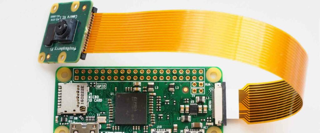
- Consumer Electronics: FPCs are widely used in smartphones, tablets, laptops, and wearable devices, enabling sleek and compact designs while providing reliable electrical connections.
- Automotive Industry: FPCs are employed in various automotive systems, such as infotainment systems, instrument clusters, and lighting applications, due to their ability to withstand vibrations and harsh environments.
- Medical Devices: The flexibility and reliability of FPCs make them suitable for medical devices, such as hearing aids, implantable devices, and patient monitoring equipment.
- Industrial Equipment: FPCs are used in industrial equipment, robotics, and automation systems, where their durability and ability to withstand harsh environments are critical.
- Aerospace and Defense: The lightweight and space-saving characteristics of FPCs make them attractive for applications in aerospace and defense systems, where weight and size are crucial factors.
Manufacturing Process of Flex Printed Circuits
The manufacturing process of FPCs involves several steps, including:
1. Substrate Preparation
The flexible substrate material, such as polyimide or polyester, is prepared and cut to the desired size and shape.
2. Copper Deposition
A thin layer of copper is deposited onto the substrate, typically through electroplating or lamination processes.
3. Photolithography
A photoresist material is applied to the copper layer, and a photomask with the desired circuit pattern is used to expose and develop the photoresist, creating the circuit design.
4. Etching
The exposed copper areas are etched away using chemical or plasma etching processes, leaving the desired circuit pattern on the substrate.
5. Surface Finishing
Additional surface treatments, such as plating or solder mask application, may be applied to protect the circuits and facilitate component assembly.
6. Component Assembly
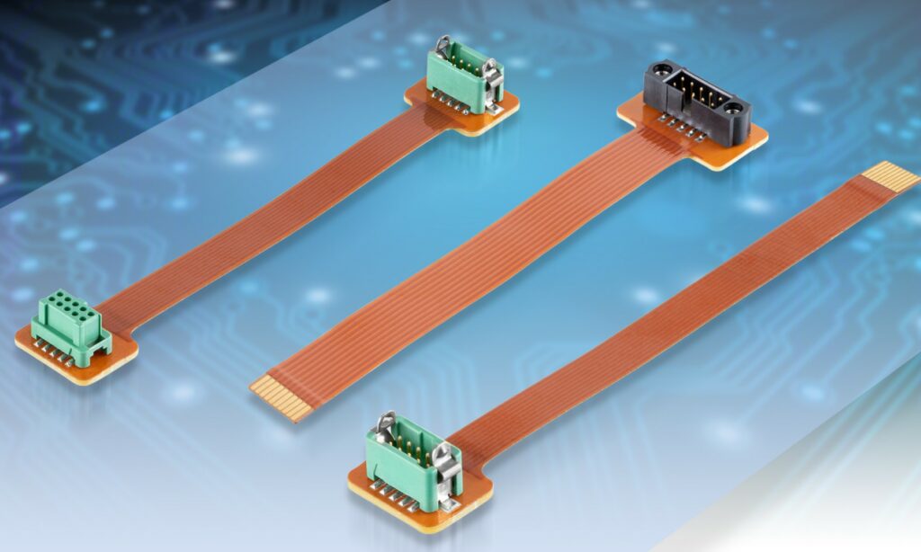
Electronic components are mounted onto the FPC using various assembly techniques, such as surface mount technology (SMT) or through-hole mounting.
7. Testing and Inspection
The assembled FPCs undergo rigorous testing and inspection processes to ensure proper functionality and quality before being integrated into the final product.
FPC Design Considerations
When designing FPCs, several factors need to be considered to ensure optimal performance and reliability:
- Bend Radius: The minimum bend radius of the FPC must be carefully calculated to prevent damage or cracking of the copper traces and substrate.
- Material Selection: The choice of substrate material, such as polyimide or polyester, depends on factors like temperature resistance, chemical resistance, and flexibility requirements.
- Trace Width and Spacing: Proper trace width and spacing must be maintained to ensure signal integrity and avoid electrical shorts or crosstalk.
- Layer Count: FPCs can be designed with multiple layers, allowing for higher circuit density and more complex routing.
- Shielding and Grounding: Proper shielding and grounding techniques may be required to protect FPCs from electromagnetic interference (EMI) and electrostatic discharge (ESD).
- Thermal Management: Adequate thermal management solutions, such as heat sinks or thermal vias, may be necessary for FPCs in high-power applications.
- Environmental Considerations: The operating environment, including temperature, humidity, and exposure to chemicals or contaminants, should be taken into account during the design phase.
FPC Reliability and Testing
Ensuring the reliability of FPCs is crucial, as they are often used in mission-critical applications or harsh environments. Various testing methods are employed to assess the performance and durability of FPCs, including:
- Environmental Testing: FPCs are subjected to extreme temperatures, humidity, vibrations, and shock to evaluate their resistance to environmental stresses.
- Flex Life Testing: FPCs are repeatedly bent or flexed to determine their flex life and identify potential failure modes.
- Electrical Testing: Electrical tests, such as continuity testing, insulation resistance testing, and signal integrity testing, are performed to ensure proper electrical performance.
- Visual Inspection: Visual inspection techniques, such as microscopy or X-ray analysis, are used to detect defects, cracks, or delamination in the FPC structure.
- Accelerated Life Testing: Accelerated life testing subjects FPCs to elevated temperatures, humidity, or other stressors to simulate long-term aging and identify potential failure mechanisms.
Future Trends in Flex Printed Circuit Technology
As technology continues to advance, FPC technology is expected to evolve and offer even more innovative solutions. Some potential future trends include:
- Miniaturization: The demand for smaller and more compact electronic devices will drive the development of FPCs with finer traces, higher circuit densities, and more layers.
- Advanced Materials: Research into new flexible substrate materials with improved thermal, mechanical, and electrical properties may lead to more robust and reliable FPCs.
- 3D and Embedded Components: The integration of 3D and embedded components directly into FPCs could enable further miniaturization and functional integration.
- Stretchable and Wearable Electronics: The development of stretchable FPCs could pave the way for advanced wearable devices and flexible electronics applications.
- Internet of Things (IoT) and 5G: The growing demand for IoT and 5G technologies may drive the adoption of FPCs in various applications due to their compact size, flexibility, and high-frequency performance.
- Printed Electronics: The integration of printed electronics techniques with FPC technology could enable the development of low-cost and disposable electronic devices.
- Sustainability and Recycling: As environmental concerns grow, there may be increased focus on developing sustainable and recyclable materials for FPCs, as well as improving the end-of-life management of these components.
Frequently Asked Questions (FQA)
- What is the difference between a flexible printed circuit (FPC) and a rigid printed circuit board (PCB)? A flexible printed circuit (FPC) is designed to be flexible and can bend, twist, or fold without compromising its electrical performance or integrity. On the other hand, a rigid printed circuit board (PCB) is made of a rigid material, such as fiberglass-reinforced epoxy, and cannot be easily bent or flexed.
- What are the advantages of using FPCs over rigid PCBs? FPCs offer several advantages over rigid PCBs, including space savings and compact design, improved reliability and durability, weight reduction, design flexibility, and potential cost-effectiveness in high-volume production runs.
- What materials are commonly used for the substrate in FPCs? The most common substrate materials used in FPCs are polyimide and polyester. Polyimide is known for its excellent thermal stability, chemical resistance, and mechanical properties, while polyester offers good flexibility and electrical performance at a lower cost.
- Can FPCs be used in high-frequency applications? Yes, FPCs can be designed and manufactured to support high-frequency applications, such as those in the telecommunications and aerospace industries. Careful consideration must be given to factors like trace width, spacing, and shielding to ensure signal integrity at high frequencies.
- How are electronic components mounted onto FPCs? Electronic components can be mounted onto FPCs using various assembly techniques, including surface mount technology (SMT) and through-hole mounting. The choice of assembly method depends on factors like component size, pitch, and the overall design requirements of the FPC.


