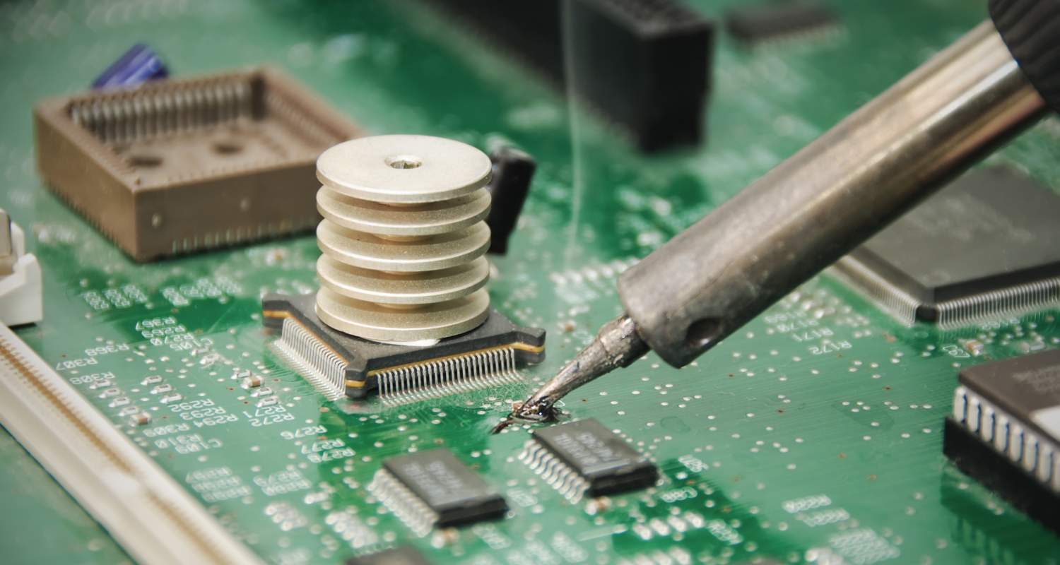
Printed circuit boards (PCBs) are fiberglass boards that act as the foundation for electronics. Attaching components to PCBs is done through a process called soldering. Soldering fuses metal components to copper pads on the board by melting metal filler material (solder) to form an electrical connection. Learning proper technique ensures your solder joints are secure and conduct properly.
This guide will cover a step-by-step process for soldering components onto a PCB using traditional tin-lead or lead-free solder.
Overview of PCB Soldering Process
Soldering a PCB involves following key steps:
- Gather Tools & Materials
- Prepare Components
- Prepare PCB
- Apply Solder Paste
- Position Components
- Apply Heat to Form Solder Joint
- Clean Residues
- Inspect Joint Quality
- Test Circuit Functionality
The following sections will detail what’s involved in each stage when soldering a printed circuit board by hand.
Step 1: Gather Tools & Materials

You’ll need the following equipment for a PCB soldering setup:
Soldering Iron – Select an iron fitted for electronics like a 60W or 80W iron or solder station with interchangeable tips. Quality brands include Weller, Hakko, Metcal.
Solder Wire – Leaded or lead-free rosin or flux-core wire. Common alloys are 60/40 tin/lead or Sn96.5/Ag3/Cu0.5. Match wire to your project metals.
Soldering Helping Hands – Third hand clip with magnifying glass helps securing PCB. Allows hands-free soldering.
Solder Wick – Braided copper desoldering wick helps remove excess solder.
Flux Pen & Isopropyl Alcohol – For pre-tinning and final cleaning.
Tip Cleaner & Sponge – Cleans oxidization and debris from iron tip while working.
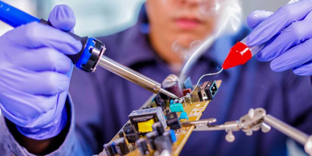
Safety – Mask, glasses, ventilation – Used during soldering for smoke and fume protection.
Step 2: Prepare Components
Preparing parts ahead ensures they’re ready for positioning and soldering onto the PCB.
- Sort all components – Have all resistors, capacitors, IC chips, connectors, etc needed arranged in trays for easy access.
- Straighten component leads – Any bent component leads should be straightened so parts sit flush to board.
- Pre-tin leads (optional) – For easier soldering, quickly apply a small amount of solder to leads beforehand.
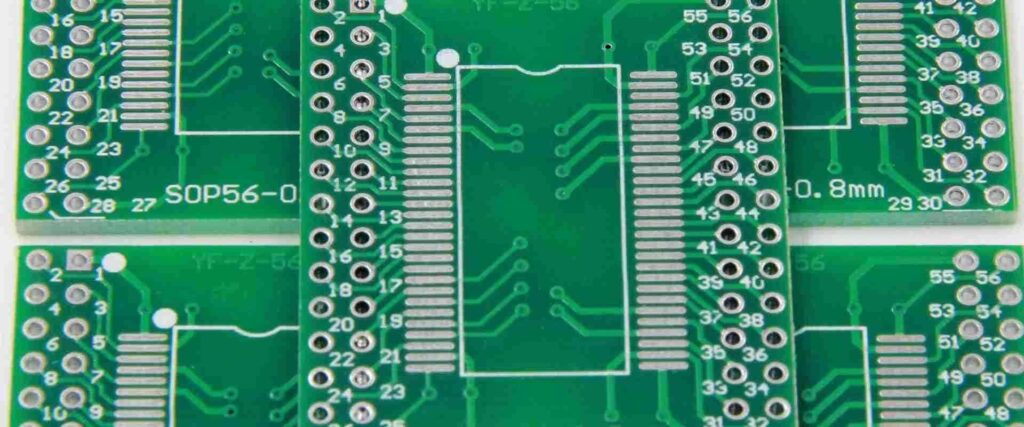
Step 3: Prepare PCB
It’s vital that printed circuit boards are clean and conductive before attempting soldering.
PCB Cleaning
- Use isopropyl alcohol (IPA) and stiff brush or toothbrush to clean all surfaces of old flux or oxidation which can cause poor electrical connections.
- Swab board with flux remover, rinse with water, and allow to fully dry.
Adding Flux
- Apply a small amount of liquid flux paste to all solder pad areas needing soldering using included flux brush. This aids wetting.
- For larger components and connectors, selectively coat one pad then manually solder that contact first to anchor component before adding flux to remaining pads.
Step 4: Apply Solder Paste (Optional)
For complex multi-pad components, solder paste allows hands-free soldering. Solder paste is an adhesive goo containing particles of solder alloy. When heated with the iron, the solder melts neatly onto pads. Follow application guidelines when using solder paste.
- Apply solder stencil – Laser cut stencils matching PCB circuit layouts allow evenly applying solder paste only onto designated pads.
- Spread paste – Use a stainless steel spreader to forcibly push a small bead of paste through stencil openings onto pads. Remove stencil.
- Alternatives – Flux pens and solder syringes allow manual application without stencils for home hobbyists.
Step 5: Position Components
With paste applied or pads prepped with flux, it’s time to accurately place components onto the PCB.
- Insert Leads – Carefully insert component leads/terminals so they fully align with their respective copper solder pads without crossing over other pads. Leads should be fully inserted to the component body without gaps between part underside and board surface.
- Hold in Place – Use helping hand clips, alligator clips, masking tape, bendable hats, or basic adhesive tack to gently secure components to board when flipping over to solder. Avoid movement. Right placement is imperative before soldering.
Step 6: Apply Heat to Form Solder Joint
With components secured, it’s soldering time. This melts the solder to create permanent electrical connections.
Ensure Proper Tip Temperature
- Set iron or station temperature to approximately 700°F (371°C) for leaded solders or 750°F (399°C) for lead-free solders. Higher for larger joints.
- Proper tip temperature ensures solder flows and melts correctly without damaging components from excess heat.
Making Solder Connections
- Touch iron tip to pad AND lead with a small amount of solder against the opposite side of iron tip. NEVER apply directly to component.
- Heat both pad and component lead simultaneously so solder melts and wets to both surfaces.
- Allow solder to flow freely onto joint as it heats before removing iron.
- Optimal joints form a “fillet” shape with concave edges as solder cools.
Solder All Joints
- Solder all remaining pads and repeats process for other components. Reapply flux or solder paste between parts.
- Visually inspect each joint after before moving to next. Resolder if needed.
- Avoid moving or bumping board till solder cools.
Step 7: Clean Residues
With all soldering complete, flux residue remains on the PCB that should be removed.
- Spray isopropyl alcohol onto board or dip soft brush into alcohol and gently scrub solder joints and component bodies to dissolve rosin residue.
- Avoid excess rubbing or pressure on joints or parts themselves.
- Thoroughly rinse board with water, allow to fully dry.
Well-cleaned PCBs help prevent electrical leakage or corrosion issues down the line.
Step 8: Inspect Joint Quality
Inspect each solder connection under a magnifying lens. Quality control evaluates your soldering abilities.
Ideally joints should display:
- Smooth fillet shape
- Shiny solder surface
- No visible pores or holes
- Good wetting of pad/lead
- No noticeable cracks
Resolder any dubious joints. Reflowing helps improve imperfect connections.
Step 9: Test Circuit Functionality
The final step verifies all your soldering efforts successfully produced a functional circuit.
- Visually inspect for any missing or improper joints, loose wires, wrong placements, etc. Double check polarity of caps/diodes.
- Power up the board and test operation. Use a mulitmeter to check for shorts.
- Recheck solder joints in problematic areas and resolder/rework as necessary.
And that completes the PCB soldering process!
Tips for Improved PCB Soldering Quality
Follow these handy tips for consistency great results:
- Keep tips clean & tinned – Prevent oxidization buildup by frequently wiping on damp sponge and re-tinning tip while working.
- Avoid moving boards till cooled – Don’t jostle or wiggle components while joints set up. Prevents cracks and fractures.
- Careful heat levels – Use just enough temperature to flow solder without prolonged overheating of pads/parts.
- Sufficient solder amounts – Little beads of solder ensure proper electrical connectivity. Too much can cause shorts or fillet cracks.
- Flux is your friend – When struggling with difficult joints that won’t take solder, flux is there to save the day.
And with that, you’re ready to churn out professional quality PCBs!
Frequently Asked Questions
Here are answers to common queries on PCB soldering:
How hot should a soldering iron be for electronics?
Around 700-800°F typically. Enough heat to melt solder rapidly without excessively overheating delicate components.
What is the best soldering iron tip for PCBs?
Fine conical pointed tips between 1-2 mm (25-30W) allow precise soldering of PCB pads and leads. Chisel tips work better for larger joints.
Is lead-free solder better for PCBS?
Lead-free solders like Sn96.5/Ag3/Cu0.5 are mandated by RoHS regulations. Higher tin content improves resistance to whiskering.
How do you remove excess solder from PCBs?
Solder wick or a quality solder sucker gently removes excess globs of solder from boards when needed without harming copper traces.
Why won’t solder stick to my PCB?
Likely causes are dirt/oxidization preventing adhesion or insufficient iron temperature to melt solder. Clean pad thoroughly and raise heat slightly till solder readily flows onto joint.


