Printed circuit boards (PCBs) form the foundation of practically all modern electronics systems today, from smartphones to fighter jets. While traditionally featuring a rectangular form factor, round shaped PCBs offer greater flexibility in an expanding range of devices where aesthetic, space savings or ergonomic needs call for non-rectilinear formats.
This article steps through the key stages, best practices, and design considerations to achieve optimum results when making round PCB circuits. Multiple prototyping and scaled production methods are detailed including the relative pros and cons of each process.
Why Produce Round Printed Circuit Boards
A partial list of circumstances motivating the fabrication of round PCBs includes:
Aesthetic Applications
- Room ambiance devices like Internet connected light switches, thermostats, speakers
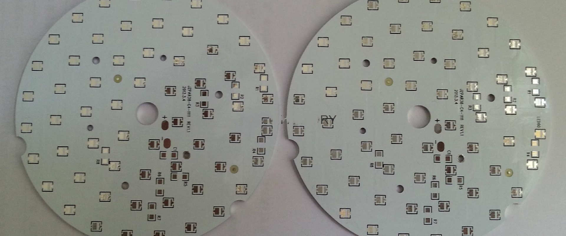
- Decorative LED lighting fixtures, mini-tors, and desk lamps
- Smart home voice assistants and control hubs
Circular Shaped Products
- Wearable electronics smartwatch or fitness tracker enclosures
- Handheld remotes, game console controllers
- Circular media players or dials
Harsh Condition Devices
- Aerospace instrument panels and engine sensor coils
- Military and surveillance circular cameras
- Automotive on-wheel tire pressure monitoring systems
Circular shapes stand uniquely qualified for creating stylish consumer gadgets and accommodating curved product profiles. They also offer structural rigidity and durability in harsh environments relative to rectangular boards. The manufacturing techniques below enable translating these design concepts into physical round PCB reality.
1. Hobbyist Round PCB Prototyping Methods

First-pass proof of concept round boards are often prototyped in personal workshops or university labs before moving into formal production processes. These methods provide adequate fidelity testing functionality with basic tools and materials on hand.
A. Manual Milling Round Blank Outlines
- Print the PCB copper layer artworks onto glossy magazine paper
- Laminate with a blank copper clad board using household iron
- Etch away copper in ammonium persulfate solution
- Carefully mill away board surrounding circuit using Dremel
- Drill holes manually
While slow and not terribly precise, this hands-on method yields custom one-off round PCB samples using common tools to validate the design. Accuracy and miniaturization greatly improve in the more advanced techniques below.
B. CNC Machining Round Boards
- Import Gerber files into CAM software – Fusion360, CamBam etc
- Machine substrate mounted on spoilboard with end mill bit to cut outline
- Automatically drill coordinate defined holes
- Allows better dimensional precision
CNC milling remains a popular intermediate step before paid fabrication to refine round PCB concepts using institutional resources. It also facilitates small batch prototyping builds.
2. Professional Round PCB Production Techniques

Once finishing proof-of-concept testing, projects progress to advanced manufacturing means through PCB fabrication partners to enable reliable volume production.
A. Die Cutting
This approach relies on rectangular panel designs arranged in arrays that maximize round PCB yields per board outline cut.
Process Steps
- Panel assembled with arrays of duplicated circuit patterns
- Rectangular panel printed and etched conventionally
- CNC die cutting machine traces round PCB profiles
- Individual boards depanelized
Benefits
- Allows high volume output
- Die precise dimensionally
- Cost effective until >3 inch diameters
Downsides
- Material wasted from rectangular panels
- Limited in size by press bed dimensions
Die cutting serves best for mass producing small form factor round PCBs thanks to its efficiency and precision.
B. V-Scoring
V-scoring partially cuts through substrate ahead of controlled snapping along defined vectors to produce rounded board shapes.
Process Steps
- Panel routed with v-shaped channels outlining circuits
- Channels create localized weak points
- Operator manually snaps boards apart along score lines
Benefits
- No bespoke tooling like custom punch dies
- Allows large format boards >10 inches
Downsides
- Stress sometimes cracks traces
- Cut accuracy tolerance ~0.5mm
- Labor intensive separating boards
While dimensionally cruder, V-scoring enables small-medium runs of bigger round PCBs where dies lack bed size capacity.
C. CNC Milling/Routing
CNC machining centers equipped with small end mill bits progressively shave away substrate to leave behind finished circuit shape.
Process Steps
- Copper clad loaded onto machining bed
- End mill bit cuts along predefined tool paths
- Machines out entire board minus traces
Benefits
- Excellent size versatility from tiny to large scale boards
- Highly accurate outline cuts +/- 0.1mm
- No hard tooling costs like punch dies
Downsides
- Relatively slow method unable to match die cutting capacities
- Requires careful fixturing to prevent substrate movement
CNC milling delivers unparalleled contour accuracy for ultra precision round PCB requirements.
Key Round PCB Layout Considerations

Certain layout provisions help facilitate manufacturing and enhance reliability of rounded circuit boards.
A. Design Rule Adjustments
- Increase annular rings to 6 mil+ help center drilling
- Widen trace widths 6+ mil handle thinner spots
- Allow 6 mil isolation gaps between traces
B. Corner Chamfers
- Route edges with rounded chamfers
- Eliminates thin wispy copper traces
- Avoids acute angle stress points
C. Stiffening Ribs
- Incorporate fiberglass stiffening ribs
- Prevent warping along rounded edges
- Maintain shape through temperature changes
By adjusting design rules and incorporating strategic features, engineers accommodate the unique challenges associated with fabricating curved PCB formats.
Comparing Round vs Rectangular PCB Boards
While non-standard shaped PCBs bring certain advantages, they also involve clear tradeoffs versus conventional rectangular boards.
| Parameter | Round PCB | Rectangular PCB |
|---|---|---|
| Manufacturability | Requires secondary machining operations – scoring/cutting/routing<br>Panels less material usage efficient | Standardized fabrication process<br>Efficient panelization yields |
| Assembly | Component placement more challenging<br>Often requires partial manual build | Highly automated SMT optimized |
| Inspection | Tends to be manual visual checks | Automated optical inspection (AOI) standardized |
| Performance | Circular boards withstand vibration better | Cost advantage, Aggravates corners vibration modes |
| Repairability | Rework difficult due to limited access | Excellent accessibility simplifies rework |
| Cost | Generally costs 2-4x rectangular boards depending on volume | Dominant PCB format achieves lowest pricing |
In situations where cylindrical aesthetics or environmental demands outweigh cost or production scalability constraints, round PCB technology proves uniquely qualified to deliver those specialized capabilities.
Testing Requirements for Round Printed Circuit Boards

Verifying the functionality and long term reliability applies equally to round PCBs as their rectangular counterparts. The sequence of quality assurance testing methods remains generally consistent:
Pre-Production Tests
- Design rule checks during layout verification
- Thermal stress modeling via simulation
- Limited prototype fabrication runs
Incoming Components Screening
- Sample electronics components for parametric and functional compliance from each manufacturer production lot
In-Process Monitoring
- Automated optical inspection after pick and place assembly
- Solder joint integrity checks via x-ray imaging
- Circuit impedance testing
Finished Board Testing
- ICT fixture validates shorts/opens across nets
- Validate dielectric isolation between traces
- Subject samples boards to temperature cycling (-40C to 100C) while monitoring operation
Ongoing Reliability Testing
- Run assembled boards for 1,000+ hours under voltage load at max ambient operating temperature
- Perform intermittent functionality checks throughout burn-in testing
- Failure analysis on units not passing burn-in reveals opportunities for continual PCB production quality improvements
While requiring some test method customization, standard quality assurance protocols apply equally to circular PCBs allowing manufacturers to back reliability claims through industry norm qualification procedures.
Future Outlook for Round Shaped PCB Boards
Expect exponential growth in round printed boards given the proliferation of smart wearables, portable IoT endpoints, home smart products and auto electronics demanding stylish circular enclosures – all requiring tightly conforming internal PCBs.
And continual advances in machining precision alongside economies of scale will further reduce costs broadening adoption scenarios of round boards. Early small scale uses often involved military aerospace applications due to the inherent stability of circular shapes against intense vibration.
We will witness consumer goods OEMs increasingly embracing round formats as EMS providers invest in enhanced production means to


