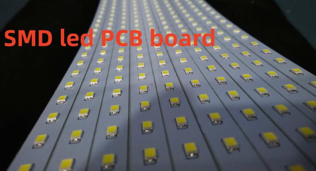
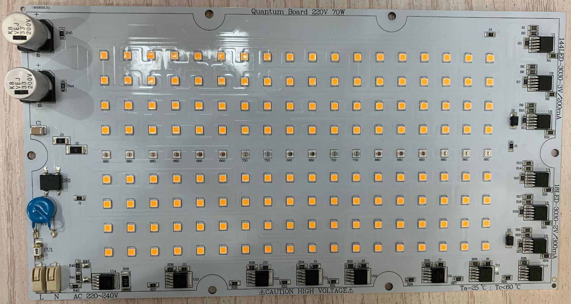
LEDs or Light Emitting Diodes are semiconductor devices that emit light when current flows through them. LEDs are becoming increasingly popular in lighting applications due to high efficiency, long life, robustness and eco-friendly nature. But using LEDs effectively requires properly designing the LED driver circuit and PCB.
Keyword: SMD LED PCB Board
This article provides a step-by-step procedure to make an LED light circuit on a custom PCB or printed circuit board using SMD LED components for more compact design over through-hole types. Key stages covered are:
- Calculating LED circuit parameters
- Selecting components
- Designing PCB layout
- Assembling and testing LED circuit
Following the guidelines helps build reliable LED light circuit boards for lighting or indication applications even with minimal experience using readily available design software and tools.
Design Considerations for LED Circuit

Below parameters need consideration when engineering LED circuits:
1. LED Operating Voltage
- Red/green/yellow LEDs – operated at 1.8-2.2V
- Blue/white – operated 3-4V
- LEDs connected serially sum voltages.
2. LED Operating Current
- Red – 20mA
- Green – 20mA
- Yellow – 20mA
- Blue – 20mA
- White – 20-30mA
- Sets LED brightness.
3. Power Supply Selection
- Match supply voltage to LED arrays.
- Additional overhead for driver loss.
- AC-DC converter or batteries can power LEDs.
4. Heat Sinking
- High power LEDs produce heat affecting life.
- LED PCB with thermal pad/external sink extracts heat.
5. Current Limiting
- Resistors limit current preventing LED damage.
- Alternate drivers – linear/switching regulators.
Considering above factors facilitates designing efficient and reliable LED light circuits.
Steps to Make LED Circuit on PCB
The key steps involved in designing and building an LED circuit PCB are:
1. Select Driver Type
Choice of LED driver influences circuit design:
- Linear current regulator – Simple, lower EMI. Not for high power
- Switch mode power supply – Efficient. Complex circuit. Higher EMI.
2. Choose Input Power Source
- AC mains supply
- Battery – lower voltage DC
3. Select LED Array Combination
- Compute operating voltage for serialization:
LED Array Selection
| Parameter | Red LED | White LED | Blue LED |
|---|---|---|---|
| Forward Voltage(Vf) | 2V | 3V | 3V |
| Operating Current(If) | 20mA | 20mA | 20mA |
- Example combinations:
- 3 red LEDs in series – 2V x 3 = 6V
- 2 blue LEDs in parallel – 3V, 20mA
- Mix LED colors based on need
4. Calculate Power Dissipation
- Input source rating should exceed LED power rating
- Power per LED – (If x Vf)
- Total power is the sum of all LEDs
5. Design Driver Circuit
- Linear regulator – resistor to limit current
- Switch mode – controller IC and discrete components
6. Determine Heat Sink Needs
- Critical for high power LED arrays
- Use PCB with thermal pad underneath
- Or add external aluminum heat sink
7. Design PCB Circuit and Layout
- Position LEDs and critical traces
- Place controller IC in center if used
- Include test points to probe circuit
8. Assemble PCB
- Solder controller IC and SMD discrete components
- Finally attach LEDs ensuring correct polarity
- Use flux for easy solder flow
9. Test LED Circuit
Verify working before full loading:
- Check assembly for shorts/dry joints
- Power up- test for expected voltage at test points
- Functionality – glowing uniform brightness
This covers the key steps that go into designing and constructing LED light circuits on PCBs from the initial component selection to final testing.
The next section illustrates this procedure for constructing an example LED circuit PCB.
Building Sample LED Night Lamp PCB

Let’s apply the steps outlined to build an LED night lamp PCB circuit powered from AC mains voltage.
Project Scope
Make a compact 10cm X 10cm PCB with 12 white LEDs operating at 12V and 500mA current requirement.
1. Select Switch Mode Driver
To achieve high brightness, an SMPS or switch mode power supply operating at high frequency provides efficient LED driving. Allows cost-effective transformer usage.
2. Input – Dual AC Voltage
Bridge rectified and filtered 220V nominal AC voltage downconverted to desired 12V level.
3. LED Configuration
- Using 1000mcd Intensity 3V white LEDs
- 12 LEDs with If = 500mA total
- Series configuration: 12 LEDs x 3Vf = 36V rating required
4. Power Dissipation
36V x 0.5A = 18 Watt is total LED power handling
5. Driver Circuit Design
Includes:
- EMI Filter – Reduces HF noise interference
- Fuse – Overcurrent protection
- Bridge rectifier – Converts AC to Pulsating DC
- Capacitor – Filters rippled voltage
- MC34063A Controller – Regulates to 12V at 500mA based on feedback
- Inductor and diode – Filters high frequency PWM ouput
- Feedback resistors – Sets output voltage
- Test points – To probe driver signals
Figure 1 – SMPS LED driver schematic diagram
6 Heat Dissipation
MCPCB used has aluminum core to conduct heat from high power LEDs and components to the board edges. Additional heat sink not required.
7. PCB Layout Design
- MC34063A driver IC placed at center of 10cm x 10cm board
- LEDs arranged peripherally and connected in series
- Feedback node test points included
- Ground fill pour ensures lower impedance
Figure 2 – Layout of the sample LED night lamp PCB
8. PCB Population
- Accurate SMD soldering using solder wire for controller IC
- LEDs can be snapped in place ensuring series connections
- Use no clean flux allowing easy component placement
9. Testing
- Bridge rectifier output – 32VDC
- IC 7V reference test point verifies operation
- LED string forward voltage – 36V
- Glow uniformly at full brightness
This covers the key steps involved in engineering the example switch mode LED driver PCB circuit with component calculations, schematic diagram and PCB layouts. Similar methods help construct other LED light circuits.
Design Software Tools for LED PCB Making

While LED circuits can be built using basic prototyping boards and tools, Fabricating professional looking PCBs along with systematic design requires CAD software.
Notable options are:
1. KiCAD EDA
Open source, freely available PCB design tool for schematic capture and board layout with community support.
2. Eagle PCB Design
Powerful commercial tool from Autodesk with free version for students and hobbyists allows professional grade PCB design.
3. Proteus Design Suite
Uses powerful simulation combining PCB with microcontroller programming. Includes component libraries suitable for LED boards.
4. OrCAD and Allegro PCB Editor
Advanced commercial tools widely used in industries suitable for high end and multilayer designs. Available as free trials.
Using such design automation software allows faster implementation once the circuit requirements are finalized.
Conclusion

This article provided a step-by-procedure to build a custom LED light circuit PCB using SMD components for compactness aided by PCB design software tools. Below key points were covered:
- Design calculations – Input/LED voltage and current
- Driver options – linear versus switch mode
- Circuit schematic design with test points
- PCB component layout considerations
- SMD soldering for reliable construction
- Final testing for functionality
Additionally, an example switch mode 12V LED night lamp PCB was designed and built to illustrate the overall process culminating in a 500mA, 10cm by 10cm ACMains powered LED light board.
Similar methods help construct LED driver boards from basic signal indication types to more complex LED panel light solutions exploiting PCB design tools for rapid prototyping. The designer can explore creative circuit topologies tailored to target application spanning lighting, automation and smart device segments.
Frequently Asked Questions
1. Can through-hole components be used when making LED PCB?
Yes, through-hole resistors and capacitors are easier to hand solder compared to SMD types. But for compact PCB, choose SMD LEDs, ICs and critical components, while supplementary elements can be through-hole.
2. Is an external light fixture required for High Power LEDs?
With 1-3W or higher LED arrays producing significant heat, an external fixture or enclosure with inbuilt heat sink helps dissipate heat through conduction and convection. The PCB itself works as a basic heat sink.
3. How is polarity of LEDs determined on PCB?
Schematic symbols and PCB silkscreen outline show LED polarity. Anode connects to the more positive voltage through series resistor, while cathode goes to ground, usually marked by flat edge of LED lens body.
4. Can AC supply be used to power LEDs?
LEDs require constant DC voltage and current limiting, Hence AC first needs conversion to DC using bridge rectifier and filter capacitors before supplying to LED driver input.
5. Why should multilayer PCB not be used for hobbyist LED boards?
While allowing high component density, multilayer PCBs require complex fabrication equipment with high cost and lead times unsuitable for prototype building. Hence reserved for mass production applications.


