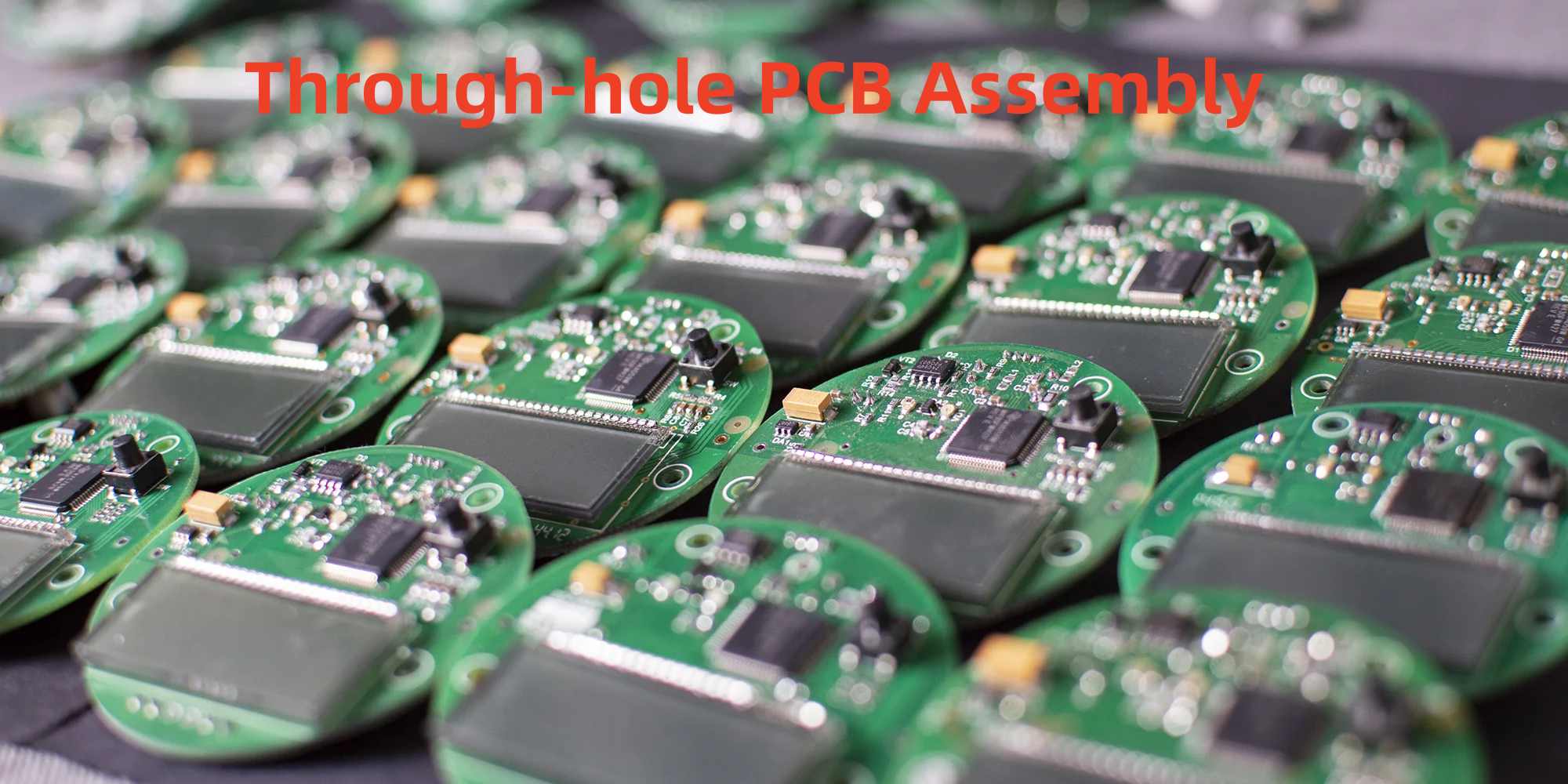
Through-hole technology refers to the mounting of electronic components on printed circuit boards (PCBs) using terminated leads called pins that pass completely through holes drilled in the board. The protruding pins are then soldered on the opposite side to form both mechanical and electrical connections.
This article provides a detailed overview of through-hole PCB assembly. We’ll examine through-hole components, PCB design considerations, soldering methods, quality inspection, advantages and disadvantages compared to surface mount technology, and more. Read on to gain expert insight into assembling PCBs using through-hole component mounting.
Overview of Through-Hole Components
Through-hole components have axial or radial leads designed to insert through corresponding holes on a PCB and soldered for mounting. Common examples include:
- Resistors
- Capacitors
- Diodes
- Transistors
- Integrated Circuits
- Connectors
- Transformers
- Relays
- Potentiometers
- Fuses
- Crystals
- Sockets
Axial leaded parts like resistors are inserted inline with their bodies while components like transistors or sockets have radial leads bending outward from the sides.
Lead diameters range from 0.4mm to over 1mm to withstand insertion and provide mechanical rigidity. Through-hole parts come in a variety of standard shapes and sizes.
PCB Design for Through-Hole Assembly

To accommodate through-hole component assembly, PCBs must be designed with the appropriate hole sizes and land patterns.
Hole Size
- Drill holes match the lead diameter usually with a +10% tolerance for fit
- Annular rings around holes provide solder adhesion
Pad Shapes
- Round, rectangular, or oval pads for leaded parts
- Thermal reliefs improve solder joint integrity
Spacing
- Sufficient clearance between pads and copper for insertion and solder flow
Plating
- Through-holes electrolessly plated with copper to facilitate soldering
Layout
- Place parts for easy insertion access without obstructing leads
Proper PCB design is crucial for reliable through-hole assembly.
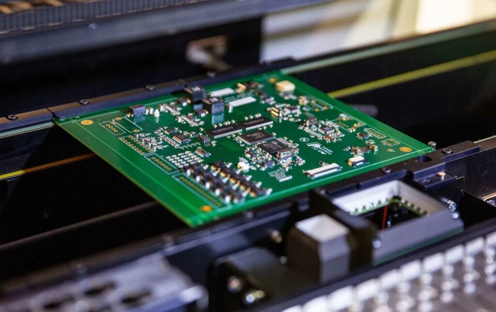
Through-Hole Component Insertion
The first assembly step is physically placing the components on the board:
- Components are hand inserted or machine placed into corresponding PCB holes
- Leaded parts are pushed fully until the body is seated against the board surface
- Confirm proper orientation and insertion depth for polarized components
- Angle dual in-line packages when inserting to avoid bending leads
- Ensure leads are not splayed out and pass through holes cleanly
- Inspect for any missing placements or incorrect parts after population
Quality insertion is critical for securing components and ensuring reliable solder joints.
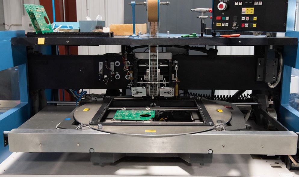
Through-Hole Soldering Methods
Components are then soldered using various techniques to form permanent mechanical and electrical connections:
Wave Soldering
- Bottom side passes over a flowing wave of molten solder
- Entire board heated as wave contacts pads simultaneously
- Very high throughput suitable for mass production
Selective Wave Soldering
- Masks block solder from sensitive areas
- Useful for mixed SMT and through-hole assemblies
Hand Soldering
- Manual soldering iron used to heat individual joints
- Flexible technique for low volume assembly
- Risk of cold joints or board damage if not careful
Reflow Soldering
- Same process as SMT reflow soldering
- Through-hole pins increase thermal mass requiring profile adjustments
Laser Soldering
- Focused laser energy to locally heat joints
- Minimal thermal impact on nearby components
- Typically only used for rework
Dip Soldering
- Immersing bottom of board in molten solder pot
- Very fast but can only be used for simple PCBs
Each soldering technique has tradeoffs between quality, flexibility, and throughput.
Inspecting Solder Joints
Verifying joint integrity after soldering through-hole components is crucial:
- Visual Inspection – Check for proper fillet shape, wetting, discoloration, pinholes
- Pull Testing – Apply gentle vertical force to ensure mechanical anchoring
- X-Ray – Images reveal hidden defects like voids or cracks
- Barrel Fill Percentage – Solder should fill at least 75% of through-hole depth
- Probe Testing – Confirm electrical connectivity and resistances match expected values
- Shear Testing – Measure force required to break solder joint
Thorough inspection safeguards against latent defects that could cause field failures.
Through-Hole Assembly Quality Control
Consistently assembling high-quality through-hole boards requires attention to:
- Soldering Profiles – Ensure temperature and time settings match parts and PCBs
- Operator Training – Skilled operators help avoid errors and board damage
- ESD Control – Grounding for staff, wrist straps, anti-static packaging
- Cleanliness – Prevent contaminants that can impede soldering
- Visual Aids – Magnification, machine vision, and x-ray aid detection of flaws
- First Article Inspection – Verify processes on initial boards using enhanced criteria
- Regular Process Audits – Periodic checks that procedures, maintenance, etc. adhere to standards
Quality discipline at each step ensures continuous production of reliable through-hole assemblies.
Through-Hole Assembly vs. Surface Mount
Comparing through-hole to surface mount assembly:
Component Size
- Through-hole parts are larger with leads requiring holes
- SMT components smaller with terminations underneath
PCB Size
- Through-hole boards larger due to component spacing needs
- SMT fits more densely without lead clearance constraints
Assembly Speed
- SMT faster to place with no lead insertion
- Through-hole manual or wave soldering reasonably fast
Reliability
- Through-hole resistant to shock and vibration
- SMT more prone to cracked joints without leads
Rework
- Through-hole allows easy part desoldering
- SMT rework is challenging without damaging boards
Cost
- SMT is lower cost at high volumes
- Through-hole economical for moderate quantities
Each approach has advantages suitable for particular applications.
Conclusion
Although surface mount dominates modern electronics, through-hole assembly persists for its simplicity, serviceability, and reliability. Understanding the intricacies of working with leaded components ensures quality through-hole PCB builds. With attention to detail in design, fabrication, soldering, and inspection, through-hole continues serving niche applications where it provides unique benefits over SMT.
Frequently Asked Questions
What are typical defects encountered with through-hole soldering?
Common defects are cold joints with insufficient wetting, overheated joints with burnt flux residue, solder bridges, voids or holes within the joint, cracked joint fillets, misaligned components, and inadequate barrel fill percentage.
What are considerations for mixed SMT and through-hole assembly?
Use selective wave or hand soldering, plan component placement so SMT parts are not shadowed from oven heating, account for different process temperatures, and allow sufficient clearance between SMT and through-hole components.
When is it better to use SMT instead of through-hole components?
For very high volume manufacturing where density and throughput matter most, surface mount is preferable. For moderate complexity consumer electronics, SMT offers a size and cost advantage.
What are typical challenges faced in through-hole rework versus SMT?
Damaging PCBs removing large through-hole parts, needing to drill out pins, challenges reheating entire joint area evenly, potential tombstoning of adjacent SMT parts, and risk of lifting or cracking pads.
What recent innovations are being made with through-hole component technology?
Some innovations are press-fit pins needing no soldering, rectangular shaped pins for added strength, hybrid SMT/through-hole packages, and selective wave soldering equipment better handling mixed assemblies.


