
Introduction
A line follower robot is a self-operating car that can detect and follow a line drawn on a surface. The path is usually indicated by a black line on a white surface or a white line on a black surface. Sensors placed under the front of the robot detect the line and send signals to the motors which steer the robot to stay on course.
Line follower robots are a fun electronics project for hobbyists and are also used in industries to transport materials between locations. They are easy to build with common electronic components and can be programmed using Arduino boards and code.
In this project, we will learn how to make an Arduino line follower robot car using the following key components:
- Arduino UNO board
- L298N dual motor driver module
- Infrared (IR) sensor module
- Chassis kit
- BO motors
- Wheels
- Battery pack
We will also go through the circuit connections, assembly process and programming required to get the robot working. So let’s get started!
Components Required
Here are the components and materials you will need to build the line follower robot:
Electronics
- 1 x Arduino UNO Board
- 1 x L298N Dual H-Bridge Motor Driver
- 2 x IR Obstacle Avoidance Sensors
- Jumper wires
- 9V Battery pack
Mechanical Parts
- 1 x Robot Chassis Kit
- 2 x BO Motors
- 2 x Wheels
- 1 x Ball Caster
Tools
- Soldering Iron
- Wire Cutters
- Screwdrivers
Circuit Diagram
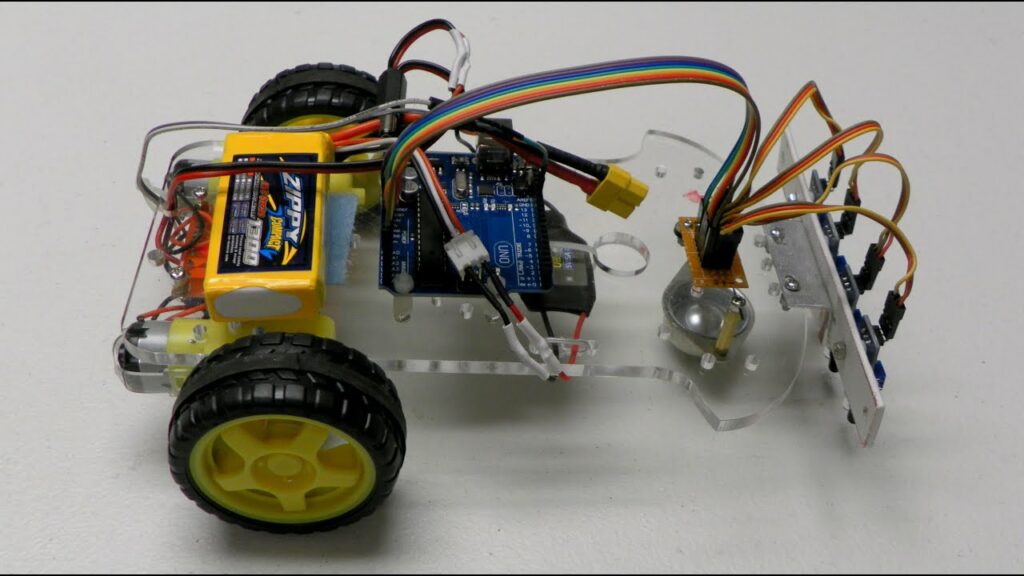
The Arduino line follower circuit mainly consists of the Arduino board, IR sensor module, L298N motor driver and two BO motors. Here is the circuit diagram:
The working of the circuit is simple:
- The two IR sensor modules are placed in the front of the chassis facing down to detect the black line on a white surface.
- The analog output pins of the IR sensors are connected to the analog input pins A0 and A1 of the Arduino.
- The digital outputs of the IR sensors are connected to digital pins 2 and 3 of Arduino.
- The Arduino processes the sensor input and controls the motion of the motors via the L298N motor driver module.
- The motors are powered separately by the 9V battery pack while the arduino and sensors are powered by the Arduino’s onboard power supply.
Let’s look at how to assemble the components onto the robot chassis next.
Assembling the Robot
The assembly process consists of mounting the Arduino, motor driver, sensors and motors onto the robot chassis. Follow these steps:
Step 1: Mount Arduino and Motor Driver
- Place the Arduino UNO board and L298N motor driver module on the top plate of the chassis.
- Drill holes into the chassis plate to secure the Arduino and motor driver in place using screw and hex standoffs.
- Use jumper wires to make connections between the Arduino, motor driver and sensors as per the circuit diagram.
Step 2: Mount IR Sensor Module
- Place the two IR sensor modules in the front section of the bottom chassis plate facing downwards.
- Make sure the IR LEDs and phototransistors are completely vertical facing the ground so they can accurately detect the line.
- Drill holes and use bolts to secure the IR sensors to the chassis bottom plate.
Step 3: Mount Motors
- Insert the gearbox shafts of the BO motors into the holes provided on either sides of the chassis.
- Use small screws to tightly secure the motors in place.
- Mount rubber wheels onto the motor shafts.
Step 4: Attach Ball Caster
1.Screw the ball caster wheel assembly to the back side of the chassis. This will provide balance and stability for the robot.
The mechanical assembly is now complete. Let’s program the Arduino next.
Programming the Arduino
The Arduino program needs to read the IR sensor values, determine which direction the line is located, and control the motors accordingly so the robot follows the line.
Here are the key steps in the program:
Include Libraries
cCopy code
#include <AFMotor.h> //Adafruit Motor Shield Library #include <Servo.h> //Servo Library
Define Pins
cCopy code
#define leftIR A0 //Left IR sensor pin #define rightIR A1 //Right IR sensor pin
Create Motor Objects
cCopy code
AF_DCMotor leftMotor(1, MOTOR12_1KHZ); AF_DCMotor rightMotor(2, MOTOR12_1KHZ);
Setup Function
Initialize motors and serial communication.
cCopy code
void setup() { //Set motor speed leftMotor.setSpeed(255); rightMotor.setSpeed(255); //Begin Serial Communication Serial.begin(9600); }
Main Loop
Read IR sensor values, check line position and adjust motor speeds accordingly.
cCopy code
void loop() { //Read sensor values int leftIRValue = analogRead(leftIR); int rightIRValue = analogRead(rightIR); //Calculate line position int linePosition = map(leftIRValue - rightIRValue, -1000, 1000, -100, 100); //Adjust motor speeds based on line position if(linePosition > 15){ //Line shifted right, slow down right motor leftMotor.setSpeed(255); rightMotor.setSpeed(200); } else if(linePosition < -15){ //Line shifted left, slow down left motor leftMotor.setSpeed(200); rightMotor.setSpeed(255); } else{ //Line in center, equal speed both motors leftMotor.setSpeed(255); rightMotor.setSpeed(255); } }
This completes the Arduino code. Download this code to your Arduino board connected to your computer via USB.
Now let’s test out the robot!
Testing the Line Follower Robot
Follow these steps to test and calibrate your Arduino line follower:
- Draw a straight black line on a white chart paper or surface. Make it sufficiently long for testing.
- Place the robot on the line and switch it ON.
- Upload the Arduino code and open the Serial Monitor window.
- Observe the sensor readings on the Serial Monitor as you move the robot across the line.
- Adjust the IR sensor positions if needed until you get accurate analog values from both sensors when on the line.
- Tune the motor speed values in code till the robot precisely follows the line at a steady speed.
- Your Arduino line follower should now seamlessly move along the line back and forth!
- Test it on curved paths and intersections to see the robot change direction based on line position.
Through calibration and code tweaks, you can improve the line tracing accuracy of the robot. Add more sensors for even better precision.
Conclusion
In this detailed DIY tutorial, we learned how to build an Arduino line follower robot using basic electronic components. The key steps included:
- Understanding the circuit connections
- Assembling the chassis, motors, sensors and Arduino
- Writing Arduino code to control motor speeds based on IR sensor readings
- Testing and troubleshooting the robot to improve line tracing accuracy
The skills gained in this project will help you expand further into more complex robotics projects involving shape following, maze solving and object avoidance. Line follower bots can also be customized further into fun hockey robots, sumo wrestling bots and more.
So go ahead and build your own Arduino line tracing car using this guide and have fun tinkering!
Frequently Asked Questions
1. What is the principle behind the working of a line follower robot?
Line follower robots work on the principle of optical sensing. IR sensor modules placed near the bottom of the robot send out infrared light and detect the amount of reflection. When on a black line, the sensors detect less reflection compared to the white surface. By detecting this change, the position of the line is determined.
2. How are the sensors and motors connected to the Arduino?
The analog pins of the IR sensors are connected to the analog input pins on the Arduino such as A0, A1 etc. The digital OUT pins of sensors are connected to Arduino’s digital I/O pins. The motors are interfaced to the Arduino via the L298N motor driver module which regulates the motor speed and direction.
3. What is a motor driver IC and why is it used?
Motor driver ICs such as the popular L298N allow easy control of motors with higher current and voltage requirements than what Arduino pins can provide directly. They act as current amplifiers to regulate speed and direction of connected motors.
4. How can the line tracing accuracy be improved?
Using more IR sensor modules, tuning the motor speed code, adjusting sensor positions, selecting the right board and chassis – all contribute to improving accuracy. Using PID control algorithms can also enhance tracing precision significantly.
5. How to prevent drifting of the line follower robot from curved paths?
Drifting trouble can be reduced by using encoders or rotary sensors on motors for accurate real-time tracking. Also, mapping wider range sensor values for curve turns helps. Lower speeds assist as well.


